Multicast TTL Planning for School Recognition Video Displays
- Home /
- Blog Posts /
- Multicast TTL Planning for School Recognition Video Displays

The Easiest Touchscreen Solution


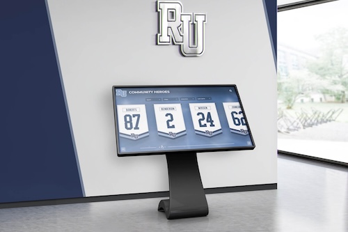
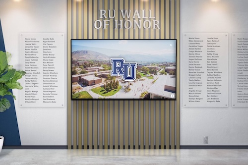
Live Example: Rocket Alumni Solutions Touchscreen Display
Interact with a live example (16:9 scaled 1920x1080 display). All content is automatically responsive to all screen sizes and orientations.
For a school recognition video display, multicast TTL (Time to Live) planning means selecting a source TTL value high enough to reach every display in the deployment—whether that is one screen in a lobby or six screens across multiple buildings—while configuring TTL thresholds on the routers at network boundaries so the recognition stream does not propagate beyond the segments where the displays live. TTL operates at Layer 3 only: it matters when a multicast packet crosses a router or Layer 3 switch boundary. On a single-VLAN deployment where displays and the content server share one subnet, IGMP snooping and a querier handle all forwarding at Layer 2, and TTL does not affect whether content reaches the displays. TTL planning becomes essential when multicast routing enters the picture—when the content server is on an administrative VLAN and the displays are on a dedicated display VLAN, or when a multi-building campus requires PIM to carry recognition streams across routed fiber uplinks.
This guide is written for school IT coordinators, athletic directors, and facilities managers commissioning recognition display installations. It explains what TTL does and does not control in a multicast network, provides practical TTL values for common school deployment patterns, covers TTL threshold configuration on the access and distribution switches most common in K-12 environments, and includes a verification table and FAQ for the scenarios where TTL misconfiguration is most likely to cause silent delivery failures.
Multicast TTL planning is one of the less visible parts of standing up a school recognition video display installation. The more prominent checks—IGMP snooping, querier configuration, VLAN membership, cable verification—address delivery within a single network segment. TTL addresses what happens at the boundary between segments: whether the recognition stream stays contained within the display network or leaks outward into broader school infrastructure, and whether it actually makes it from the source to displays on a routed segment.

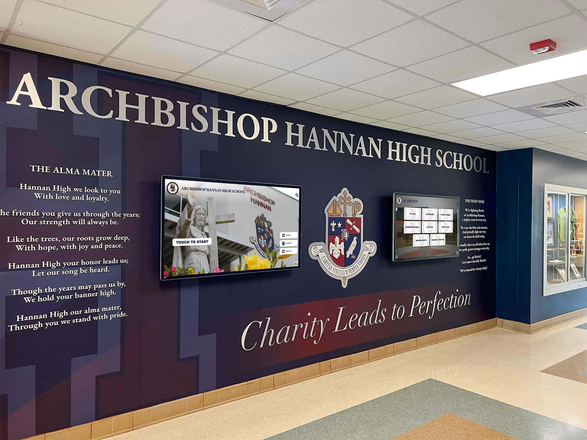
Recognition displays integrated into school hallway murals depend on reliable content delivery—when multicast routing is involved, TTL planning controls whether the stream reaches the display and whether it stays scoped to the intended network segments
What TTL Controls in Multicast Networks
The Time to Live field is an 8-bit value in the IP packet header. Every IP packet carries one. For unicast traffic, TTL’s primary function is loop prevention: each router that forwards a packet decrements the TTL by one, and any packet whose TTL reaches zero is dropped. For multicast traffic, TTL serves an additional function: scoping.
A multicast-capable router running PIM (Protocol Independent Multicast) or a similar multicast routing protocol will only forward a multicast packet out a given interface if the packet’s TTL exceeds the TTL threshold configured on that interface. By default, most interfaces have a threshold of 0, meaning any packet with TTL ≥ 1 is forwarded. Raising the threshold on specific interfaces creates a boundary: a packet with TTL 15 will not cross an interface configured with TTL threshold 16. This is TTL scoping.
For school recognition video displays, this mechanism has two practical dimensions:
Source TTL. The content server or media delivery application sets the TTL on multicast packets it generates. A source TTL of 1 means packets are dropped at the first router they encounter—appropriate only when all displays share a subnet with the content server and no routing is involved. A source TTL of 16 allows the stream to cross one or more routing hops within the campus while remaining containable by TTL threshold configuration at the campus edge.
Router TTL threshold. On the routers and Layer 3 switches that connect the display VLAN to broader campus or district infrastructure, a TTL threshold set above the source TTL creates a hard boundary. Multicast packets from the recognition display content server cannot cross that boundary regardless of routing table entries or PIM neighbor relationships. This is the administrative mechanism schools use to prevent a recognition stream from leaking onto unrelated segments.
What TTL does not control: TTL has no effect on multicast forwarding within a single Layer 2 segment. IGMP snooping and the querier handle all multicast group management and port-level forwarding at Layer 2. A packet with TTL=1 arriving at a switch with IGMP snooping enabled is forwarded correctly to display ports that have joined the multicast group—TTL is only examined when the packet reaches a router interface. IGMP querier configuration and IGMP snooping testing address that Layer 2 dimension independently of TTL planning.
When TTL Matters for School Recognition Video Displays
On most small school recognition display deployments—a single lobby kiosk or a hallway with two or three screens, all on the same VLAN as the content server—TTL planning is not the critical factor. IGMP snooping and querier configuration control everything at Layer 2, and even a packet with TTL=255 sent from the content server is handled correctly at the switch without ever crossing a router.
TTL planning becomes directly relevant in any of the following configurations:
Separate VLANs for content server and displays. Many schools place administrative and AV equipment on separate VLANs for security segmentation. If the content server for the recognition platform lives on the main school network or an AV production VLAN, and the displays are on a dedicated display VLAN, the recognition stream must cross a Layer 3 boundary between VLANs. A Layer 3 distribution switch acts as the multicast router for this crossing, and its interface TTL thresholds determine what traffic crosses.
Multi-building campus with routed fiber uplinks. High schools and K-12 campuses with multiple buildings frequently connect buildings over fiber using routed links. If recognition displays are distributed across buildings—lobby screens in Building A, athletic wing displays in Building B, gymnasium entrance screens in Building C—the multicast stream from a content server in the main building must traverse inter-building routing. Without TTL threshold configuration at building boundaries, that stream can propagate wherever PIM distributes it across the campus.
District WAN connectivity. Schools on a shared district WAN or MPLS network need explicit TTL or PIM scope boundaries to prevent a single school’s recognition display stream from propagating to other schools on the same WAN. A recognition video stream from one high school’s content server reaching an elementary school’s switches on the same district network is a common example of TTL scope leakage that TTL threshold configuration at the district WAN edge would have prevented.
Cloud-hosted platform with a local media gateway. Some recognition display platforms deliver content from a cloud endpoint that terminates at a local media gateway on the school’s network. If the gateway then redistributes content to displays over local multicast, the source TTL on those re-originated packets needs to be set based on the school’s routing topology, not inherited from cloud platform defaults.

Multi-screen hallway installations where displays span routed segments require TTL planning to ensure each screen receives the stream while containing the multicast traffic within intended boundaries
TTL Values and Scoping Conventions
TTL scoping for multicast was formalized as a mechanism in RFC 2365 (Administratively Scoped IP Multicast), though RFC 2365 ultimately recommends administrative address-based scoping (the 239.0.0.0/8 range) over TTL scoping alone. TTL thresholds remain widely deployed on campus networks as a practical scoping layer. The conventional TTL ranges for campus and enterprise deployments—which predate RFC 2365 and are referenced in its historical discussion—are:
| TTL Range | Conventional Scope | Applicability for School Recognition Displays |
|---|---|---|
| 0 | Same host only | Not used for display delivery; packets never leave the originating device |
| 1 | Same subnet/LAN segment | Appropriate only when content server and all displays share one subnet with no routing |
| 2–15 | Site-local (small area) | Suitable for single-building deployments with one or two routing hops |
| 16–31 | Site scope (medium campus) | Suitable for multi-building campuses where recognition streams should stay within the main campus |
| 32–63 | Regional scope | Used when displays span a district-wide network with multiple campuses |
| 64 and above | Wide-area scope | Not appropriate for school recognition displays; no K-12 deployment requires this range |
These ranges are conventional guidelines, not rigidly standardized boundaries. The operative principle is that a packet’s effective TTL after decrement at each hop must remain above the threshold on any interface it needs to cross, and below the threshold on any interface that should block it.
For school recognition video displays, the practical guidance is:
Set the source TTL to at least the number of routing hops between the content server and the furthest display, plus one. If the content server and displays are on different VLANs separated by one Layer 3 switch, a minimum source TTL of 2 is required; a value of 16 provides ample headroom for most single-campus deployments while remaining within site scope.
Configure TTL thresholds at campus edge routers and district WAN interfaces to a value above the source TTL. If source TTL is 16, set the TTL threshold on the uplink interface to the district WAN to 17 or higher. Packets with TTL ≤ 16 are never forwarded across that interface even if PIM has a route to the destination.
Do not rely solely on TTL scoping as the only isolation mechanism. TTL scoping prevents unintended propagation at correctly configured router interfaces, but it does not replace VLAN segmentation or PIM scope configuration. For school recognition programs with strict network governance requirements, TTL scoping should be one layer of a defense-in-depth approach that also includes administrative scoping with the 239.0.0.0/8 address range and VLAN segmentation.
Planning TTL for School Recognition Display Deployments
The following table summarizes TTL planning decisions for the most common school recognition display deployment patterns. The actual routing hop count between the content server and each display determines the minimum viable source TTL; the values below are practical starting points, not universal minimums.
| Deployment Pattern | Content Server Location | Display Location | Routing Hops | Recommended Source TTL | TTL Threshold on WAN/District Uplink |
|---|---|---|---|---|---|
| Single building, single VLAN | Display VLAN | Display VLAN | 0 (no routing) | Any value; TTL not examined at L2 | N/A |
| Single building, separate VLANs | Admin or AV VLAN | Display VLAN | 1 (one L3 switch) | 4–8 | Set ≥ source TTL + 1 on district uplinks |
| Multi-building campus | Central MDF | Displays in 2–3 buildings | 1–3 | 16 | Set ≥ 17 on district WAN uplinks |
| District WAN, multiple schools | District media server | Displays at each school | 3–5 | 32 | Configure scope boundaries at each school’s edge |
| Cloud gateway rebroadcast | Local media gateway | Displays on display VLAN | 1–2 | 4–8 | Set ≥ source TTL + 1 at campus edge |
Planning a Recognition Display Installation?
If your school is designing a recognition display network and wants to understand how multicast delivery, VLAN segmentation, and content platform requirements interact with your specific infrastructure, a live walkthrough addresses those details directly. Schedule a free demo with Rocket Alumni Solutions to see the platform and discuss network requirements before your installation begins.
Configuring TTL Thresholds on Common School Network Equipment
TTL threshold configuration is available on most enterprise-grade routers and Layer 3 switches. The following guidance covers platforms commonly deployed in K-12 environments. Always consult your specific platform’s current documentation before applying any configuration.
Cisco IOS and IOS-XE
On Cisco IOS, the TTL threshold on a multicast-enabled interface is set with:
interface <interface-type> <number>
 ip multicast ttl-threshold <value>
This command sets the minimum TTL a multicast packet must exceed to be forwarded out that interface. A packet arriving with TTL equal to the threshold is not forwarded; it must be strictly greater. For example, to prevent multicast traffic with TTL ≤ 16 from being forwarded out a WAN uplink:
interface GigabitEthernet0/0
 ip multicast ttl-threshold 16
A multicast packet with source TTL 16 arrives, the router decrements it to 15, and then checks: 15 > 16? No. The packet is dropped. A packet with source TTL 18 arrives, is decremented to 17, and 17 > 16 passes—the packet is forwarded.
To verify the current TTL threshold on an interface:
show ip interface <interface-type> <number>
Look for the Multicast TTL threshold line in the output.
To verify which multicast streams are actively being forwarded by PIM:
show ip mroute
This displays the multicast routing table with each source address, group address, incoming interface, and outgoing interface list. Use this to confirm recognition display streams are being forwarded to the correct outgoing interfaces and not to interfaces where they should be blocked.
To confirm PIM is enabled on the SVIs serving both the content server VLAN and the display VLAN:
show ip pim interface vlan <display-vlan-id>
PIM must be enabled on both the source-side and destination-side Layer 3 interfaces for the routing to function.
Cisco Meraki
Meraki does not expose a direct TTL threshold configuration through the standard Meraki dashboard. Multicast scoping on Meraki networks is managed through IGMP snooping configuration per-network, PIM configuration on MX appliances if multicast routing is required, and firewall rules that can block multicast group address ranges from propagating between segments.
For schools using Meraki infrastructure that need TTL-based scoping, the practical approach is to rely on VLAN segmentation and firewall rules at the MX appliance to contain recognition display streams, rather than TTL thresholds that are not directly configurable through the dashboard.
HPE Aruba
On HPE Aruba switches and gateways with multicast routing enabled, TTL threshold configuration is applied under the routing interface for the relevant VLAN. Consult the Aruba CX or ArubaOS documentation for the specific command syntax for your platform version, as it differs between the ProCurve/2930 lineage and the Aruba CX lineage. The show ip mroute equivalent on Aruba platforms displays the multicast routing table for verification.
Ubiquiti UniFi
UniFi does not provide native TTL threshold configuration for multicast through the standard management interface. On UniFi Security Gateway (USG) or UniFi Dream Machine devices that run an underlying EdgeOS or similar platform, TTL threshold syntax may be available via SSH, but UniFi does not surface it in the standard GUI and the setting may be overwritten by future firmware updates.
For UniFi-based school networks, the recommended approach for recognition display multicast scoping is to combine administrative scoping using the 239.0.0.0/8 address range with VLAN segmentation and IGMP snooping, rather than relying on TTL threshold configuration that requires unsupported CLI modification.
Lobby recognition installations that combine physical and digital elements may be on a dedicated display VLAN separate from the content server—TTL threshold configuration on the Layer 3 boundary between VLANs prevents the multicast stream from propagating beyond intended segments
School-Specific TTL Planning Scenarios
Event Night Preparation: Verifying TTL Before a Recognition Ceremony
Before a hall-of-fame induction night, sports banquet, or graduation recognition event, confirming that multicast routing is functioning correctly—and that TTL values are as designed—takes under 10 minutes and prevents the class of failure where content appears on some screens but not others. A router reconfigured during summer break may have lost its TTL threshold settings, causing the recognition stream to behave differently than it did at the end of the previous school year.
Run these verification commands from the Layer 3 switch serving the display VLAN before each major recognition event:
show ip mroute <multicast-group-address>
Confirm the display VLAN’s interface appears in the outgoing interface list (OIL). If the display VLAN is absent from the OIL, PIM is not distributing the stream to that segment—either because no IGMP Join has been received from the display VLAN, because PIM is not enabled on the SVI for the display VLAN, or because a TTL threshold is blocking the forward.
show ip interface vlan <display-vlan-id>
Look for the Multicast TTL threshold value. Verify it is not set above the content server’s source TTL. A threshold of 0 (the default on most platforms) allows all multicast with TTL ≥ 1 to be forwarded into the VLAN.
For school recognition programs timed to the academic calendar—fall sports hall-of-fame nights, homecoming recognition walls, and end-of-year ceremony displays—this pre-event check is the network equivalent of confirming display power and content currency. A passing result on all three checks (IGMP snooping active, querier present, PIM forwarding with no blocking TTL threshold) means the multicast delivery path is ready.
Summer Infrastructure Rebuilds and TTL Configuration Loss
School IT teams commonly rebuild switch and router configurations during summer break. A Layer 3 switch that had correct TTL threshold settings in the spring may lose those settings after a firmware upgrade, configuration template application, or switch replacement. TTL threshold configuration is a line in the IOS running configuration—if the running configuration is not saved or a template omits these lines, they disappear on reload.
After any summer rebuild affecting the distribution or access switches serving recognition displays:
- Verify PIM is re-enabled on the SVIs for both the content server VLAN and the display VLAN
- Confirm the TTL threshold on the display VLAN SVI is not set above the content server’s source TTL
- Confirm the TTL threshold on the district WAN uplink is set above the source TTL to maintain the scope boundary
- Verify multicast group membership using
show ip igmp groupson the display VLAN SVI
This is particularly important for schools managing recognition content that goes live at the start of the school year—fall sports season launches, back-to-school lobby recognition activations, and opening-day hall-of-fame displays where content delivery needs to be working from day one without a troubleshooting call.
Multi-Building Campus: Preventing Cross-Building Stream Leakage
On a multi-building campus, each building’s distribution switch is typically a Layer 3 boundary. If PIM is running across buildings—so that recognition streams from a content server in the main building can be distributed to displays in auxiliary buildings—those same PIM neighbor relationships can carry the stream beyond the intended scope if TTL thresholds are not configured at building boundaries.
The recommended approach for multi-building school campuses:
- Set source TTL on the content server sufficient to cross the maximum number of inter-building routing hops (typically 16 for a campus with up to 14 building-level routing boundaries)
- Configure the TTL threshold on the district WAN uplink at each building’s edge router to a value above the source TTL (for example, threshold 17 if source TTL is 16)
- Use a multicast group address in the 239.0.0.0/8 administrative scoping range for the recognition display stream to add a second scoping layer that is independent of TTL
For school campus recognition programs with displays spread across buildings—lobby screens at the main entrance, hallway recognition boards in the athletic wing, and gymnasium entry displays—TTL planning ensures each building receives the stream while inter-district links do not carry school-specific recognition traffic outside the campus.
Content Server Source TTL Misconfiguration
The most common TTL-related failure in school recognition display networks is the content server’s source TTL being set too low, not router threshold misconfiguration. Many operating systems default to TTL=1 for multicast socket creation, which means the packet is dropped at the first router it encounters. A content server on one VLAN sending to displays on a different VLAN with source TTL=1 will appear to work during Layer 2 testing on the same VLAN, but fail entirely once the displays are placed on the production display VLAN.
To check the source TTL on a Linux-based content server or media gateway, run a packet capture on the server’s NIC and inspect the TTL field in multicast packets leaving the server:
tcpdump -i <interface> -v dst net 224.0.0.0/4 | grep ttl
On Windows-based content servers, the multicast TTL is set per-socket by the application. Check the recognition display platform’s documentation for its TTL configuration option, or use a packet capture tool to inspect outgoing TTL values directly.
Resolving a source TTL=1 problem typically means reconfiguring the content platform’s multicast TTL setting, overriding the TTL at the OS network level, or placing the content server on the same VLAN as the displays to eliminate the routing boundary entirely.

Recognition screens in school hallways depend on content delivery working reliably across any routing boundaries between the content server and the display—source TTL misconfiguration is one of the less visible causes of content that stops updating without any visible on-screen error
TTL Verification Table for School Recognition Video Displays
Use this table when commissioning a new recognition display installation or after any infrastructure change affecting the multicast delivery path between the content server and the display VLAN.
| Verification Check | How to Verify | Pass Criteria | Common Failure |
|---|---|---|---|
| Content server source TTL | Packet capture on server NIC; filter for multicast destination (224.0.0.0/4) | TTL > number of routing hops to furthest display | TTL=1 default; packets dropped at first router |
| PIM enabled on content server VLAN SVI | show ip pim interface vlan <id> | PIM mode shown; interface listed as PIM-enabled | PIM not enabled; no multicast routing between VLANs |
| PIM enabled on display VLAN SVI | show ip pim interface vlan <id> | PIM mode shown; display VLAN SVI PIM-enabled | Display VLAN not participating in PIM |
| Multicast stream in routing table | show ip mroute <group> | Entry present; display VLAN SVI in outgoing interface list | No mroute entry; stream not being forwarded to display VLAN |
| TTL threshold on display VLAN SVI | show ip interface vlan <id> — check Multicast TTL threshold | Threshold = 0, or less than (source TTL minus routing hops) | Threshold set above source TTL; packets dropped at display VLAN SVI |
| TTL threshold on WAN/district uplink | show ip interface <uplink> — check Multicast TTL threshold | Threshold > source TTL (blocks scope leakage outward) | Threshold = 0 (default); stream leaks to district WAN |
| IGMP group membership on display VLAN | show ip igmp groups vlan <id> | Display endpoints listed for recognition stream group address | No group members; displays not sending IGMP Join |
| End-to-end content delivery | Observe display content | Recognition content animating normally | Content not updating; delivery path broken at some layer |
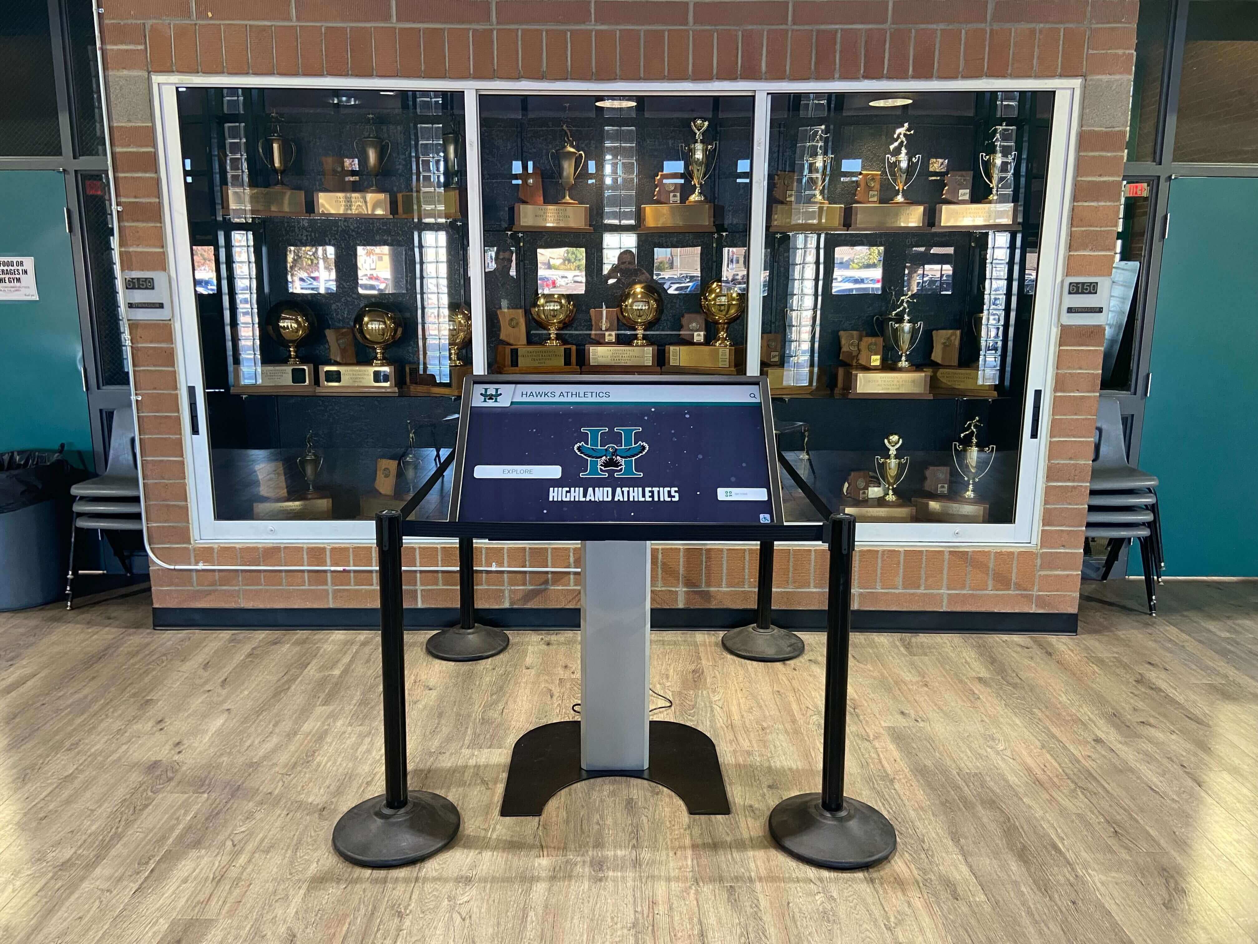
Confirming that content is displaying correctly on the recognition screen is the practical end-to-end test that validates the entire multicast delivery path—from the content server's source TTL through routing and IGMP snooping to the display port
FAQ: Multicast TTL for School Recognition Video Displays
Does TTL affect multicast delivery when all displays and the content server are on the same VLAN?
No. TTL is only examined when a multicast packet reaches a router interface. Within a single VLAN—where a Layer 2 switch handles all forwarding—IGMP snooping and the querier determine which ports receive multicast traffic. A packet with TTL=1 and a packet with TTL=255 are treated identically by the IGMP snooping switch. TTL planning is only relevant when multicast packets must cross a Layer 3 boundary between VLANs or subnets.
What is the default source TTL on multicast packets from recognition display content servers?
This varies by platform and operating system. Many media delivery applications explicitly set the multicast socket TTL, often to 1 or to the OS default (commonly 64 or 128 on Linux distributions when no specific multicast TTL is set, though this varies). Some operating systems apply a separate default for multicast sockets that is lower than the unicast TTL default. The safest approach is to run a packet capture on the content server’s NIC and inspect actual TTL values in outgoing multicast frames rather than relying solely on documentation.
Can I use TTL scoping as the only mechanism to prevent recognition display streams from reaching other school buildings?
TTL scoping is a soft boundary. It prevents packets from crossing router interfaces where the TTL threshold has been correctly configured, but it does not prevent forwarding on misconfigured interfaces, does not stop Layer 2 bridges from carrying traffic within a segment, and does not prevent a future infrastructure change from inadvertently opening a TTL path. For stronger isolation, combine TTL scoping with administrative scope addresses from the 239.0.0.0/8 range, PIM scope configuration, and VLAN segmentation. TTL scoping should be one layer of protection, not the only one.
What should I do if recognition displays on a separate VLAN are not receiving any multicast content?
Work through the multicast delivery path in sequence: (1) confirm IGMP snooping and querier are configured on the display VLAN; (2) confirm PIM is enabled on the SVIs for both the content server VLAN and the display VLAN; (3) run show ip mroute on the Layer 3 switch and confirm the recognition display group address has an entry with the display VLAN’s SVI in the outgoing interface list; (4) if the display VLAN SVI is absent from the OIL, confirm the displays are sending IGMP Joins and that no TTL threshold on the display VLAN SVI is blocking the forward; (5) if no mroute entry exists at all, confirm the content server’s source TTL is greater than 1 and that PIM is receiving traffic from the content server’s VLAN SVI. A source TTL=1 at the content server is a common cause of step (3) failure—the stream never crosses the routing boundary.
How do I find the multicast group address my recognition display platform uses?
Run a packet capture on the content server’s NIC or on the display VLAN during a scheduled content delivery. Filter for multicast destination addresses (the 224.0.0.0/4 range). The group address the platform uses for content distribution will appear as the destination IP of frames originating from the content server. Check your platform vendor’s network integration documentation for officially documented group addresses; this information is typically part of the infrastructure requirements guide provided to IT administrators.
Does multicast TTL interact with IGMP querier configuration?
Not directly. The IGMP querier sends General Membership Queries to 224.0.0.1 (all-hosts); these are local-scope messages that by convention carry TTL=1 and do not cross routers. The querier operates at Layer 2 within the display VLAN. TTL planning is relevant to the multicast content stream—the recognition video itself—not to the IGMP control-plane messages the querier uses to maintain group membership. A correctly configured querier on the display VLAN functions independently of the content stream’s source TTL.
Should TTL planning be documented as part of the recognition display installation record?
Yes. Document the content server’s source TTL, the TTL thresholds configured on the Layer 3 switch interfaces (content server VLAN SVI, display VLAN SVI, and the district WAN uplink), the PIM mode in use, and the multicast group address. Include this alongside the IGMP querier IP address, query interval, and VLAN IDs in the site documentation. When the school’s IT staff or an AV integrator returns to troubleshoot or expand the installation, knowing the intended TTL configuration prevents misdiagnosis of TTL-related delivery failures as IGMP or hardware issues.
Conclusion: TTL Planning as Part of a Complete Multicast Configuration for School Recognition Displays
TTL planning is one component of a complete multicast configuration for school recognition video displays. It is a concern for deployments where multicast routing is involved—when the content server and displays span separate VLANs, when displays are distributed across a multi-building campus connected by routed fiber, or when a district WAN creates a boundary that recognition streams should not cross. For single-VLAN deployments, IGMP snooping and querier configuration address everything at Layer 2, and TTL is not the limiting factor.
For schools expanding their recognition display programs from a single lobby kiosk to a campus-wide installation across multiple buildings, TTL planning is the bridge between the Layer 2 IGMP configuration that works for the initial single-screen deployment and the Layer 3 multicast routing configuration required for the larger one. Getting it right before the fall semester—before the first hall-of-fame induction night, the first homecoming, the first championship recognition ceremony—means the displays run without intervention through every event on the school’s calendar.
Schools investing in recognition displays that honor athletes, scholars, and faculty across hallways, lobbies, and athletic facilities deserve a network foundation that keeps those displays updated reliably through every season and recognition event. A well-configured multicast delivery path—with IGMP snooping, an active querier, PIM-enabled SVIs, and correctly scoped source TTL values—is that foundation.
For schools planning to add recognition displays for varsity programs and program milestones and looking to understand the complete infrastructure requirements before installation, a walkthrough with the recognition platform team covers not just content management and display hardware but the network configuration that keeps content flowing reliably.
Ready to See a Recognition Display System Built for School Networks?
Rocket Alumni Solutions designs interactive hall-of-fame touchscreens, digital honor walls, and athletic recognition kiosks that integrate with managed school network environments. If your school is planning a recognition display installation and wants to walk through multicast delivery requirements, VLAN segmentation, and infrastructure prerequisites with a team that understands school IT constraints, schedule a demo to see the platform running and discuss your network configuration before the installation begins.
Request a free demo with Rocket Alumni Solutions to see the complete system in action.
Live Example: Rocket Alumni Solutions Touchscreen Display
Interact with a live example (16:9 scaled 1920x1080 display). All content is automatically responsive to all screen sizes and orientations.