

A recognition display stream compression test verifies that Display Stream Compression (DSC) is correctly negotiated between your source device and the recognition panel, and that high-resolution athlete video, highlight reels, and animated award graphics play back without blocking artifacts, color banding, or edge halos. DSC is a VESA-standardized visually lossless compression codec built into DisplayPort 1.4+ and HDMI 2.1 interfaces—it enables 4K and higher-resolution content to travel over cable runs and signal paths whose raw bandwidth would otherwise require a lower resolution or a dropped frame rate. When DSC negotiation succeeds and the codec operates correctly, the compression is invisible. When it fails—through a firmware mismatch, a cable that cannot sustain the required bandwidth, or a receiver that partially implements the standard—the result is visible corruption on exactly the content that matters most: a championship video loop playing in the lobby during an induction ceremony.
This guide is written for school IT coordinators, AV staff, athletic directors, and facilities teams responsible for recognition wall installations, interactive hall-of-fame kiosks, and athletic lobby display systems. It covers when DSC is negotiated, a step-by-step stream compression test procedure, source and receiver verification, artifact detection for video content, a results interpretation table, and common failure patterns with corrective actions.
High-resolution recognition displays running game highlights, athlete portrait slideshows, and animated record-board graphics put more sustained demand on the display signal path than most school technology environments ever encounter. A 4K panel showing static slides at 30 Hz passes link training without strain. The same panel playing a 60 Hz highlight reel during a packed gym event, with the source device pushing compressed video through a 50-foot cable run through conduit, is a different signal problem entirely—and it is the scenario where unvalidated DSC negotiation produces the most visible failures.

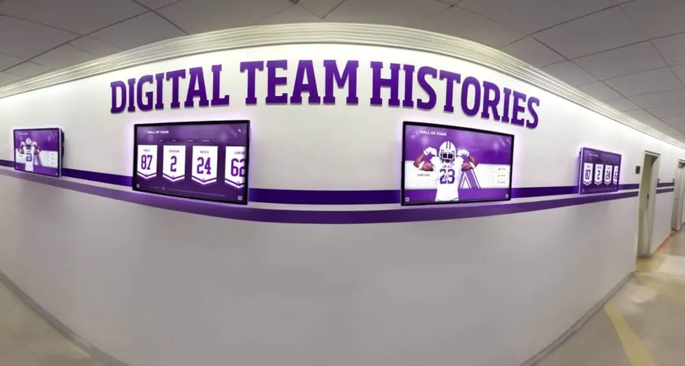
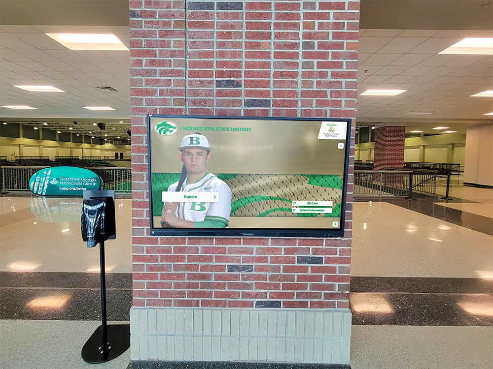
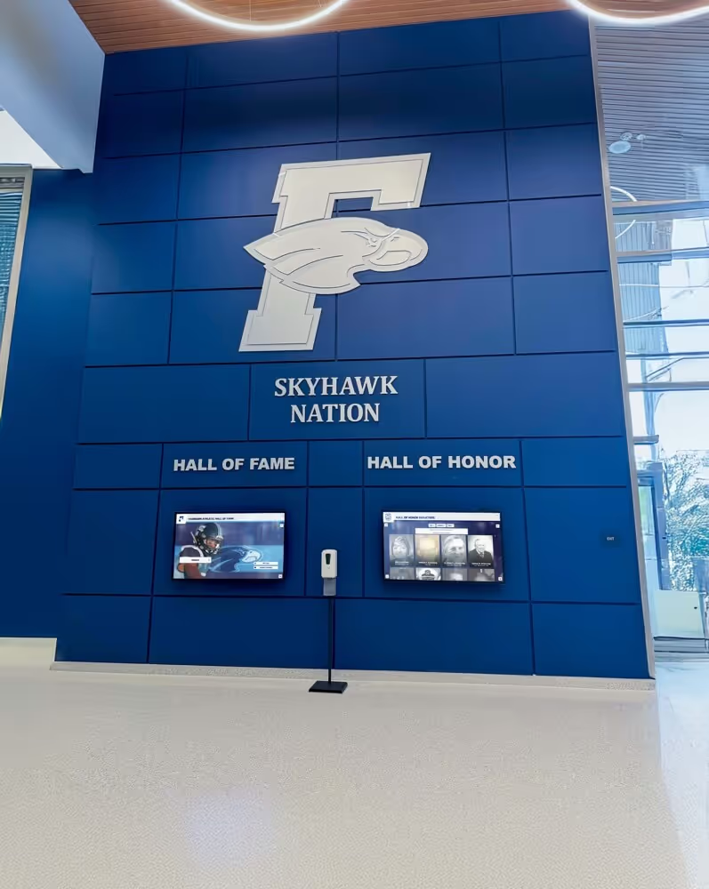
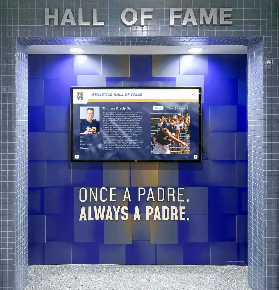
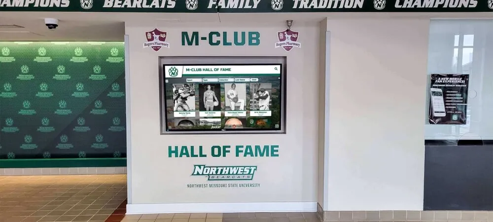
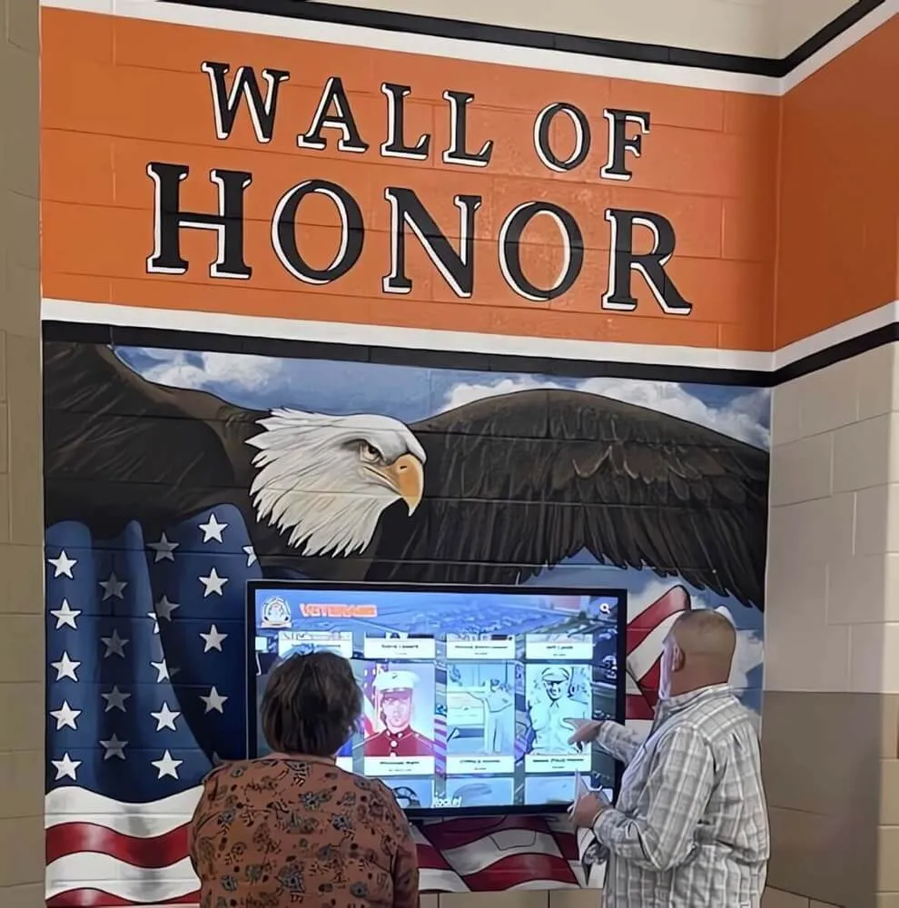
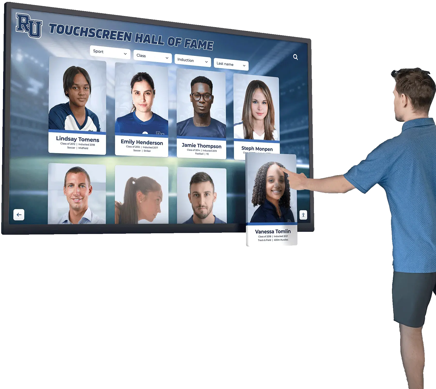
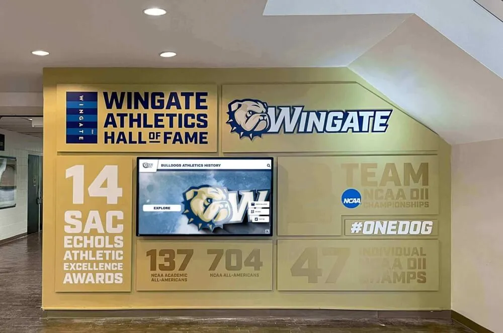
School lobby recognition screens playing sports highlight video at full 4K resolution depend on correctly negotiated Display Stream Compression—a stream compression test before an event prevents artifact-corrupted playback during live ceremonies
What Display Stream Compression Does and When It Is Negotiated
Display Stream Compression is a standardized, low-latency image compression codec defined by VESA and adopted into DisplayPort 1.4, DisplayPort 2.0/2.1, and HDMI 2.1. It is not proprietary—it is part of the interface specification—and it operates transparently when both source and receiver support it and the link training process determines that raw bandwidth is insufficient for the target resolution and refresh rate combination.
DSC is negotiated during link training. On DisplayPort, the source device reads the sink device’s DSC capability through the DPCD (DisplayPort Configuration Data) auxiliary channel before committing to an output mode. If the panel advertises DSC support and the bandwidth required for the target resolution at the target refresh rate exceeds what the link can carry uncompressed, the source activates DSC and compresses each frame before transmission. The receiver decompresses and displays. If the panel does not advertise DSC support—or if the source driver does not read the capability correctly—the system either falls back to a lower resolution, drops to a lower refresh rate, or fails to display an image.
On HDMI 2.1 with DSC, the negotiation occurs during the EDID handshake and subsequent HF-VSDB (HDMI Forum Vendor-Specific Data Block) parsing. The source reads DSC capability from the sink’s EDID and activates compression for modes that require it. HDMI 2.1 DSC support varies by panel firmware version, and panels that shipped with incomplete firmware may report DSC capability in the EDID but fail to decompress correctly at runtime.
The following table shows the interface conditions under which DSC is typically negotiated on recognition display installations, so IT and AV staff can identify immediately whether their deployment is operating in a DSC-active mode before starting the full test sequence.
| Interface | Resolution / Refresh Rate | DSC Negotiated? | Notes |
|---|---|---|---|
| DisplayPort 1.4 (HBR3) | 4K @ 60 Hz, 8-bit, 4:2:0 | Possible, not always required | Bandwidth is tight; depends on color format and panel |
| DisplayPort 1.4 (HBR3) | 4K @ 60 Hz, 10-bit, 4:4:4 | Required | Raw bandwidth exceeds HBR3; DSC is the only path |
| DisplayPort 1.4 (HBR3) | 8K @ 30 Hz | Required | Raw bandwidth exceeds HBR3 maximum |
| DisplayPort 2.1 (UHBR10/13.5/20) | 4K @ 120 Hz, 10-bit | Not required at UHBR20; may activate at lower rates | High bandwidth headroom reduces DSC dependency |
| HDMI 2.1 | 4K @ 120 Hz | Required | Exceeds HDMI 2.0 bandwidth ceiling; DSC fills the gap |
| HDMI 2.0 (18 Gbps) | 4K @ 60 Hz, 8-bit, 4:2:0 | Not required | Within bandwidth limit |
| HDMI 2.0 (18 Gbps) | 4K @ 60 Hz, 10-bit, 4:4:4 | Not supported | Exceeds bandwidth; DSC not available on HDMI 2.0 |
For most school recognition display installations, the relevant scenarios are DisplayPort 1.4 at 4K/60 Hz and HDMI 2.1 at 4K/120 Hz. Both are active DSC territory when running full-color, high-refresh-rate content.
Pre-Test Prerequisites and Equipment
Run through this checklist before beginning the stream compression test. Each item is a dependency; skipping any one of them produces results that cannot be trusted.
| Prerequisite | Verification Step | Why It Matters |
|---|---|---|
| Source device with DisplayPort 1.4+ or HDMI 2.1 output | Check the GPU or system spec sheet | DSC requires interface support on both source and sink; older interfaces cannot activate DSC |
| Display panel with confirmed DSC support | Check the panel’s product spec sheet or EDID dump | Some panels advertise high resolution without DSC, limiting what modes are achievable |
| Cable rated for target interface bandwidth | Check cable packaging: DP 1.4 requires 32.4 Gbps; HDMI 2.1 requires 48 Gbps for full bandwidth | An underrated cable is the single most common DSC failure cause in field installations |
| Updated GPU driver and panel firmware | Confirm driver version against manufacturer’s DSC support notes | DSC codec bugs are a known issue in older GPU drivers; firmware updates on panels fix EDID and DSC decompressor bugs |
| Test video content at target resolution and refresh rate | Prepare a 4K/60 Hz or 4K/120 Hz test clip with fast horizontal motion | Static images do not exercise the DSC codec; only moving content reveals blocking artifacts and decompression errors |
| Access to GPU driver control panel or DisplayPort AUX reader | Intel Graphics Command Center, AMD Radeon Software, or NVIDIA Control Panel | Required to read the negotiated output mode and confirm DSC status |
| Maintenance window or pre-event window | Coordinate with recognition program administrator | The test involves output mode changes that may briefly interrupt display content |
If the source device is a dedicated digital signage player or media appliance rather than a PC, locate the player’s diagnostic or system information screen—most commercial signage platforms report the current output resolution and signal format in their status menus, which is sufficient for verifying the negotiated mode even without GPU driver tools.
Step 1: Identify the Currently Negotiated Output Mode and DSC Status
Before running any content tests, determine what output mode the source device has negotiated with the display panel. This step tells you whether DSC is active and whether the negotiated mode matches the intended operating point for your recognition display installation.
On Windows with an NVIDIA GPU:
Open NVIDIA Control Panel → Display → Change Resolution. The current resolution and refresh rate appear in the active display list. To check DSC status specifically, open the NVIDIA Display Container LS or use the nvidia-smi command-line tool and look for DSC-related output in the display information. NVIDIA’s driver logs (accessible via the Event Viewer under the NVIDIA-related providers) also record DSC negotiation outcomes during link training.
On Windows with an AMD GPU:
Open AMD Radeon Software → Display. The active display shows the negotiated resolution and refresh rate. AMD’s Display Information page (accessible via the gear icon next to the active display) reports the pixel encoding format and, on Radeon RX 5000 series and later with current drivers, the DSC status.
On Windows with an Intel integrated or Arc GPU:
Open Intel Graphics Command Center → Display → Display Information. The negotiated output format is listed. On Intel Arc systems with DisplayPort 1.4 output, the Graphics Command Center reports the active DSC state when the driver activates compression.
Cross-platform EDID and DPCD reading:
The open-source tool edid-decode (available for Linux; Windows ports exist) parses the EDID data from the connected display and reports the DSC capability advertised by the panel, including the supported slice counts and bits-per-component. Comparing the EDID-advertised capability against the driver’s reported active mode is the most direct method to confirm that DSC negotiation completed successfully rather than falling back silently.
What to record from this step:
- Active resolution and refresh rate
- Color encoding format (4:4:4, 4:2:2, or 4:2:0) and bit depth (8-bit or 10-bit)
- Whether the driver reports DSC active or inactive
- The EDID-reported panel DSC capability (maximum slice count, minimum slice width)
If the driver reports a lower resolution or refresh rate than intended—for example, 4K/30 Hz when 4K/60 Hz was configured—the system fell back due to a bandwidth constraint. The most common cause is a cable that does not meet the bandwidth rating for the target interface. Proceed to Step 2.

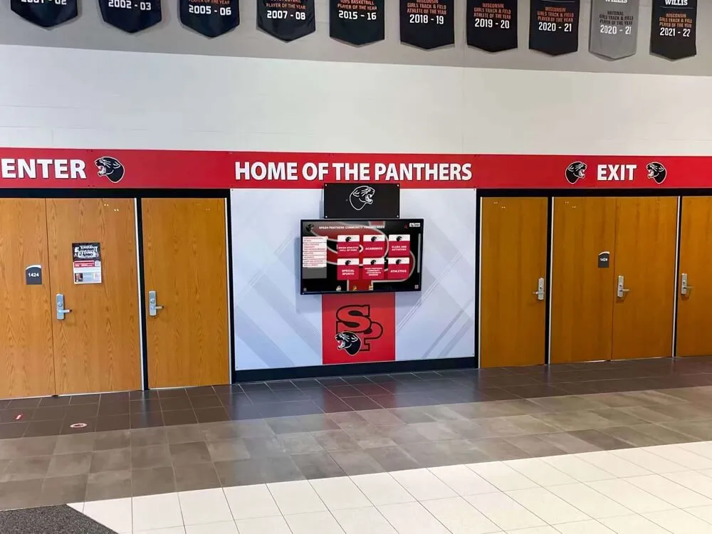
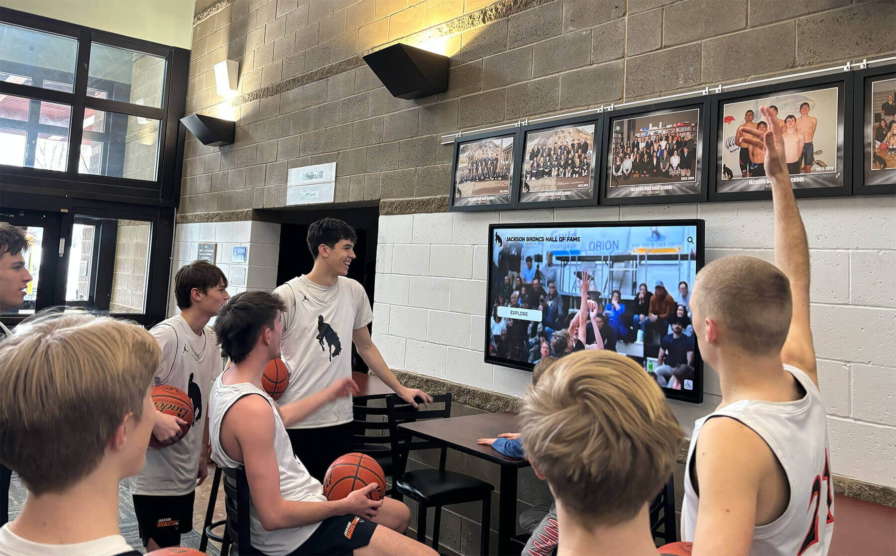
Multi-screen recognition display installations require DSC negotiation to succeed independently on each display—a cable or receiver firmware issue on one panel can cause that screen to fall back to a lower resolution while adjacent screens display correctly
Step 2: Cable and Signal Path Verification
A cable that cannot sustain the bandwidth required for the negotiated interface spec is the most common cause of DSC negotiation failure and stream compression artifacts in field installations. This step isolates the cable and signal path before testing the source or receiver independently.
Passive cable length limits by interface:
| Interface | Bandwidth | Reliable Passive Cable Length | Notes |
|---|---|---|---|
| DisplayPort 1.4 (HBR3, 32.4 Gbps) | 32.4 Gbps | Up to 2–3 meters (passive) | Longer runs require active or optical cables |
| HDMI 2.1 (48 Gbps) | 48 Gbps | Up to 1–2 meters (passive) | Passive cables degrade rapidly beyond 1 meter at full 48 Gbps; active or fiber required |
| HDMI 2.0 (18 Gbps) | 18 Gbps | Up to 5–7 meters (passive) | Ratings vary by cable quality; certified Premium HDMI cables are rated to 10 meters |
| Active DP or HDMI optical cable | Varies by model | 10–100 meters | Signal is converted to optical fiber; immune to passive length limits |
If the installed cable run exceeds the passive length limit for the interface, substitute a known-good active or optical cable for the test. Run the active cable directly between the source and display, bypassing any wall runs, conduit pulls, or HDMI extenders. If the negotiated mode and DSC status improve with the substitute cable, the installed cable is the root cause.
Testing extenders and matrix switches:
Recognition display installations frequently route the signal through HDMI extenders (balun pairs over Cat6) or HDMI matrix switches that allow multiple sources to share multiple displays. These components have their own bandwidth ratings and DSC support characteristics. Many HDMI-over-Cat6 extenders are rated for HDMI 2.0 at 18 Gbps, not HDMI 2.1 at 48 Gbps—which means a source sending a DSC-encoded HDMI 2.1 signal through an HDMI 2.0-rated extender will lose frames or produce output corruption at the extender’s output.
Verify each component in the signal chain against the bandwidth requirement for the target mode. Remove the extender or matrix switch and connect the source directly to the display for the initial cable verification test. If the negotiated mode is correct with a direct connection and fails through the extender, the extender is the limiting component.
Connector and seating inspection:
Before concluding that a cable is under-rated, physically inspect the connectors on both ends. HDMI connectors that are partially unseated by cable management stress, cable tension at the display mount, or repeated plug/unplug cycles from shared-use installations present symptoms identical to an under-rated cable: intermittent signal loss, fallback to lower resolution, or periodic blanking during content transitions. Apply gentle forward pressure to each connector while observing the display output—a change in display state during connector pressure confirms a seating issue rather than a cable bandwidth problem.
Step 3: Receiver and Display Firmware Verification
Once the cable and signal path pass the Step 2 verification, the next test target is the display receiver’s DSC decompressor. DSC decompression is handled in the panel’s display controller silicon, and implementation quality varies across panel manufacturers and firmware versions. A panel that correctly decompresses DSC-encoded content on its initial firmware may develop regressions in subsequent updates, or may have shipped with known decompression bugs that a firmware update addresses.
Finding the panel firmware version:
On most commercial displays, the firmware version appears in the panel’s on-screen menu under System Information, About, or a similar label. The menu path varies by manufacturer; consult the product’s admin guide if the information is not immediately visible.
Checking for available firmware updates:
Navigate to the display manufacturer’s support portal and search for the panel’s model number. DSC-related firmware updates are typically labeled in release notes as “DSC stability improvements,” “4K signal reliability,” or “display compression fix.” Compare the installed firmware version against the latest available version before concluding that a DSC decompression artifact is a hardware limitation rather than a firmware defect.
Testing with a DSC bypass mode:
Some GPU drivers allow DSC to be disabled explicitly for a specific display, forcing the link to operate at reduced bandwidth (lower resolution or refresh rate) without compression. If the DSC-active mode produces artifacts and the DSC-disabled mode (at reduced resolution) is clean, the decompression path is the source of the artifact—not the cable or the codec negotiation. This narrows the corrective action to firmware update, panel replacement, or mode selection adjustment.
Recognition displays serving as the centerpiece of a school’s hall-of-fame program—particularly those installed as part of a formal academic recognition program where consistent visual quality reflects institutional quality—benefit from this firmware verification step before any public event, not only when an artifact is first observed.
See How Rocket Designs Recognition Displays for AV Reliability — Book a Demo
Step 4: Artifact Detection Tests for High-Resolution Video Content
With the signal path verified and DSC negotiation confirmed, the final test phase exercises the codec under recognition display content conditions. Static images and simple slideshows do not stress the DSC decompressor in ways that reveal decompression defects. High-resolution video—particularly content with fast horizontal motion, sharp color transitions, and high-contrast edges—is required to surface block artifacts, color banding, and edge halos that indicate a DSC codec problem.
Test content requirements:
The test video should include all of the following content types, as each stresses the codec differently:
- Fast horizontal panning across high-contrast graphics (athlete names, jersey numbers, school branding)
- Slow-motion video with fine texture detail (grass, court surface, uniform fabric)
- High-contrast color transitions (team colors against white backgrounds, dark locker room footage cutting to bright field footage)
- On-screen text with sub-pixel rendering (small stat overlays, date and record text)
- Smooth gradient backgrounds (common in recognition template design)
A 2–4 minute clip combining these elements provides sufficient codec exercise for a recognition display stream compression test. School recognition video libraries that include game highlight reels, coach tribute montages, and championship ceremony footage typically contain all required content types without needing purpose-built test material.
Artifact types to observe during playback:
| Artifact | Description | Visual Pattern | Likely Cause |
|---|---|---|---|
| Block boundary artifact | Rectangular grid visible in the image | 8x8 or larger blocks appear as brightness or color steps at boundaries | DSC slice-count mismatch between source and receiver |
| Color banding | Smooth gradients appear as visible steps | Gradient backgrounds show 4–8 distinct bands instead of smooth transitions | Bit-depth reduction in the DSC encoding path; 8-bit content encoded at reduced precision |
| Edge halo | Bright fringe around high-contrast edges | White or colored outline visible around athlete names, jersey numbers, or logo text | DSC filter overshoot at high-contrast transitions; often indicates an incorrect slice width configuration |
| Periodic blanking | Screen goes black for 1–3 frames, then recovers | Brief blackout during fast content transitions | Bandwidth transient that the cable cannot sustain at peak; often occurs at scene cuts in highlight video |
| Partial-screen corruption | One region of the screen shows correct content, another shows a corrupted band | Horizontal or vertical band of garbled pixels, consistent position across multiple frames | Receiver DSC decompressor slice-channel error; firmware update or panel replacement required |
| Pixelation during motion | Fast-moving subjects appear lower resolution during motion, then sharpen when they stop | Applies only to the moving object or region; static background remains sharp | Dynamic bit-rate allocation in the DSC encoder under-serving high-motion regions; reduce color depth or disable motion-adaptive DSC settings if available |
Observation method:
Position a second observer at a distance representative of the typical viewing distance for the installation—lobby kiosks are typically viewed from 4–12 feet, hallway recognition walls from 6–15 feet. Many DSC artifacts that are visible in close-up inspection during the test are not visible at normal viewing distance, and vice versa: some block artifacts that appear subtle at close range are clearly visible in wide-angle viewing where the eye integrates across the panel surface.
Record timestamps from the test video where each artifact type appears, and photograph or video-record the panel surface during those moments for documentation. This record allows the IT team to reproduce and verify the artifact after any configuration or firmware change.

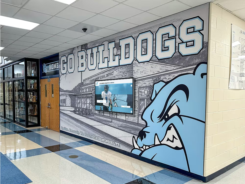
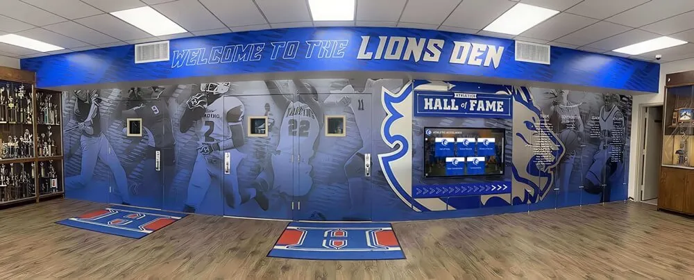
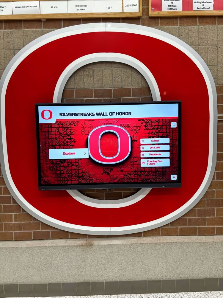
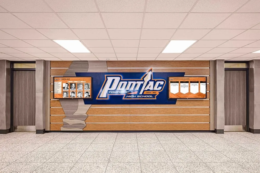
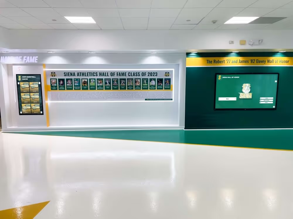
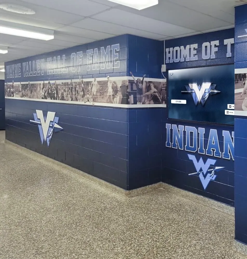
Recognition displays integrated into athletic hallway installations are often the most visible element of a school's recognition program—DSC artifact detection testing ensures the video quality matches the quality of the content and the occasion
Step 5: Sustained Load and Thermal Verification
A recognition display that passes the initial artifact detection test under a short clip may still fail during a continuous two-hour event loop. DSC decompression hardware can exhibit thermal-dependent behavior: the decompressor operates correctly at startup and ambient temperature, but produces artifacts or resets after extended operation at display brightness and ambient temperature conditions typical of a packed gym or warmly lit lobby.
Running a sustained load test:
Schedule the test video to loop continuously for 90–120 minutes at the display’s operational brightness setting (not demo mode or energy-saver mode). Observe the display at 30-minute intervals, recording any artifact onset or display reset. A display that produces no artifacts during the first 30 minutes but develops block boundary artifacts after 60 minutes is exhibiting a thermal-dependent DSC decompressor instability.
Environmental considerations for recognition display installations:
Commercial and educational displays installed in direct sunlight exposure from lobby windows, in gymnasiums with high ambient temperature, or in tight equipment enclosures can experience elevated panel temperatures that do not occur in controlled testing environments. If the installation location experiences seasonal temperature variation, run the sustained load test during the warmest part of the school day and in the warmest anticipated seasonal conditions.
What to do if thermal artifacts appear:
- Verify the installation has adequate air circulation around the panel and mounting hardware
- Check that cable management does not block ventilation slots on the display or media player
- Review whether the media player (if it is the compression source) is also thermally stressed and reducing GPU clock speed during the sustained test
- Contact the panel manufacturer with the artifact video, firmware version, and thermal conditions; thermal-dependent DSC decompressor instability is a known failure mode and is sometimes addressed by firmware updates
For programs managing recognition displays in gymnasiums and athletic facilities where events generate significant ambient heat and humidity, coordinating display installation with facilities staff to ensure adequate ventilation is as important as the signal-path validation steps. Schools planning athletic awards galas and recognition events that feature lobby and hallway recognition screens as part of the event environment should include a thermal soak test in their pre-event checklist.
Interpreting Stream Compression Test Results
Use this table to map the outcome of each test step to a corrective action.
| Test Step | Expected Result | Failure Indication | Corrective Action |
|---|---|---|---|
| Step 1: Negotiated mode and DSC status | Driver reports DSC active at target resolution and refresh rate | Driver reports lower resolution, lower refresh rate, or DSC not active | Check cable bandwidth rating; update GPU driver; verify panel EDID advertises DSC capability |
| Step 2: Cable and signal path | Direct connection with a rated cable achieves target mode; extender maintains signal | Mode falls back or signal drops with extender or long run | Replace cable with active or optical; replace extender with a model rated for the target interface and bandwidth |
| Step 3: Receiver firmware | No artifacts after 5-minute playback of test content; firmware is current | Artifacts present with a verified cable; firmware is outdated | Apply manufacturer’s latest firmware; test artifact presence after update; if artifacts persist on current firmware, escalate to manufacturer support |
| Step 4: Artifact detection | No block, banding, halo, or blanking artifacts during full test video | Any artifact visible during artifact-type list content | See artifact-type table above for specific cause and corrective action |
| Step 5: Sustained load | No artifact onset or display reset during 90-minute loop | Artifacts appear after 30–60 minutes of continuous operation | Address thermal conditions; investigate thermal-dependent DSC decompressor instability; contact manufacturer |
A test that passes all five steps confirms that DSC is correctly negotiated, the signal path can sustain the required bandwidth, the receiver decompresses correctly, and the installation is stable under sustained operation. Document the results—including the negotiated mode, DSC status, cable model and length, panel firmware version, and GPU driver version—as the baseline for future regression testing.
Common DSC Failures in Recognition Display Environments
Failure: Source negotiates a lower resolution than the panel’s native resolution
This is almost always a cable bandwidth failure. The source reads the panel’s EDID capability (which correctly advertises DSC support at the target mode), activates DSC, begins link training, and the cable cannot sustain the required bandwidth. The link training algorithm falls back to a mode that fits within the cable’s actual capability, which may be 1080p/60 Hz or 4K/30 Hz instead of the intended 4K/60 Hz. Replacing the cable with a certified active cable resolves this failure in the large majority of cases.
Failure: DSC active but block boundary artifacts appear consistently in the same screen region
A block boundary artifact that is geometrically consistent—always appears at the same horizontal or vertical position in the image—indicates a slice-count or slice-width mismatch between the source encoder and the receiver decoder. The DSC standard supports multiple slice-count configurations; the source and receiver must agree on the same configuration during link training. If they negotiate different configurations (a driver bug or EDID parsing error can cause this), the decoder produces artifacts at the slice boundaries. Updating the GPU driver and panel firmware resolves this in most cases. If it does not, check whether the panel’s DSC capability advertisement (via EDID) accurately reflects the decompressor’s actual slice support.
Failure: Periodic blanking during scene cuts in highlight video
A recognition display that briefly blacks out during scene transitions—cuts from court footage to locker room footage, or from a championship graphic to a player portrait—is experiencing a bandwidth transient that exceeds what the cable or extender can sustain at that moment. Scene cuts in compressed video require the codec to reset and begin encoding a fresh scene, which briefly produces a higher bitrate burst than steady-state motion video. An HDMI 2.1 cable rated at 40 Gbps instead of 48 Gbps may pass most content cleanly but fail at these peak moments. Replace the cable with a certified 48 Gbps HDMI 2.1 cable and re-run the test with the same content.
Failure: Artifacts appear on one display in a multi-screen installation but not others
A multi-screen recognition installation where one panel shows artifacts while adjacent panels are clean almost always indicates a panel-specific issue: different firmware version on the affected panel, a receiver DSC decompressor defect, or a cable or extender issue specific to that panel’s signal path. Verify the firmware version on the affected panel against the others, and substitute the cable and extender to isolate which component is the root cause.
For school recognition programs managing installations across multiple buildings or zones—donor walls, athletic hall-of-fame screens, and lobby recognition kiosks that share a content management platform but use independent signal paths—the multi-panel consistency check is an important part of any pre-event AV validation. Programs featuring dual donor and hall-of-fame recognition systems on separate panels often benefit most from a per-panel DSC verification step since each display may have been installed and commissioned at a different time.
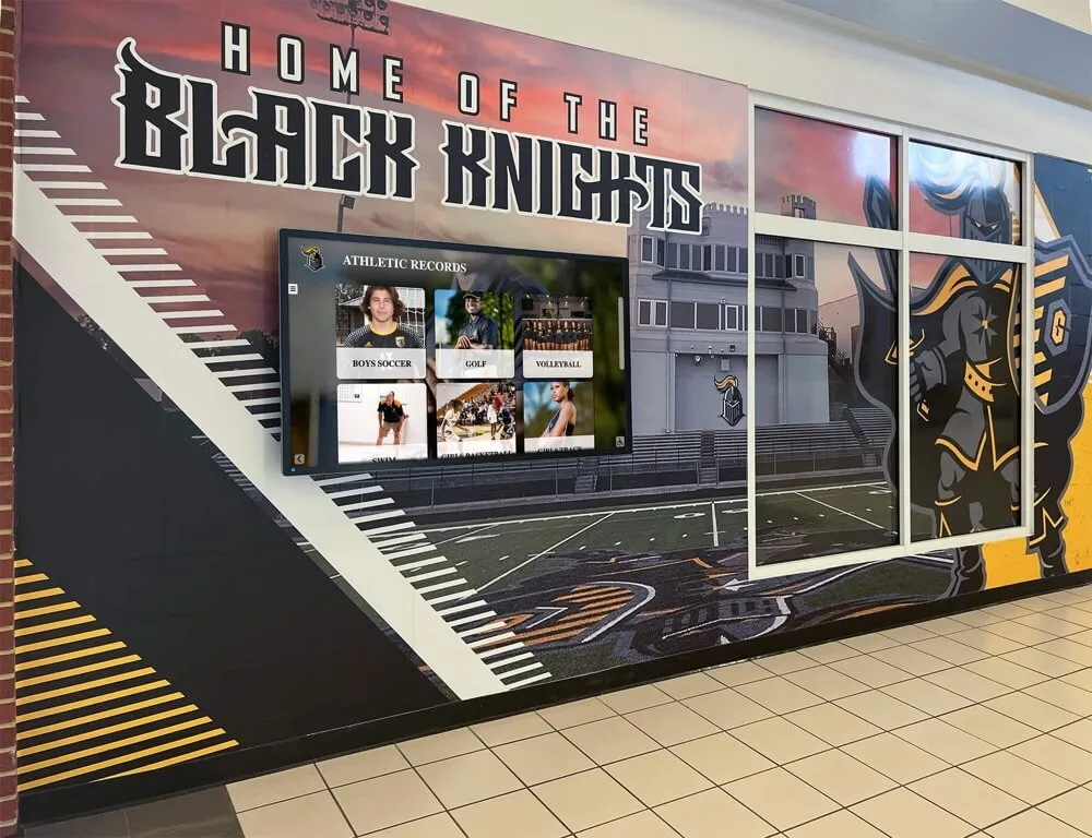
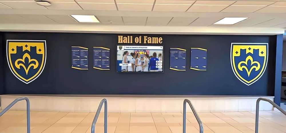
Each display in a multi-panel recognition installation has its own signal path, cable run, and receiver firmware—a DSC stream compression test must verify each panel independently, not just the first or most accessible one
How DSC Testing Connects to the Broader Recognition Display Signal Chain
Display Stream Compression does not operate in isolation—it is one layer of a signal chain that includes the source device, the GPU driver, the cable and any extenders, the panel input circuitry, the display controller, and the panel firmware. A well-executed recognition display stream compression test is most valuable when it fits within a broader AV validation workflow that also addresses the connection layer (HDMI-CEC configuration for automated display control) and the physical signal integrity layer.
Schools managing recognition displays for long-term program archives—where content spans multiple athletic generations, college tour touchscreen deployments, and multi-year donor recognition programs—benefit from maintaining a DSC validation record alongside the content management and update schedule. A display that was validated in September and receives a firmware update in December may need re-validation, particularly if the release notes mention any display signal or compression changes.
For recognition programs that use slide content as well as video—senior shoutout slideshows combined with championship highlight reels, for example—note that DSC artifact testing on static slides is not a substitute for video content testing. The DSC codec is designed to handle high-entropy image data, and it is the codec’s response to motion and scene changes that most often reveals decompression defects.
Athletic recognition programs in particular tend to add new content that stresses the signal chain more over time: what began as a static portrait display often grows to include auto-ranking scoreboards, video highlights, and multi-sport interactive browsing. Schools building long-term recognition infrastructure should design the signal chain for the highest-demand content anticipated over the display’s operational lifetime, not only the content deployed at installation.
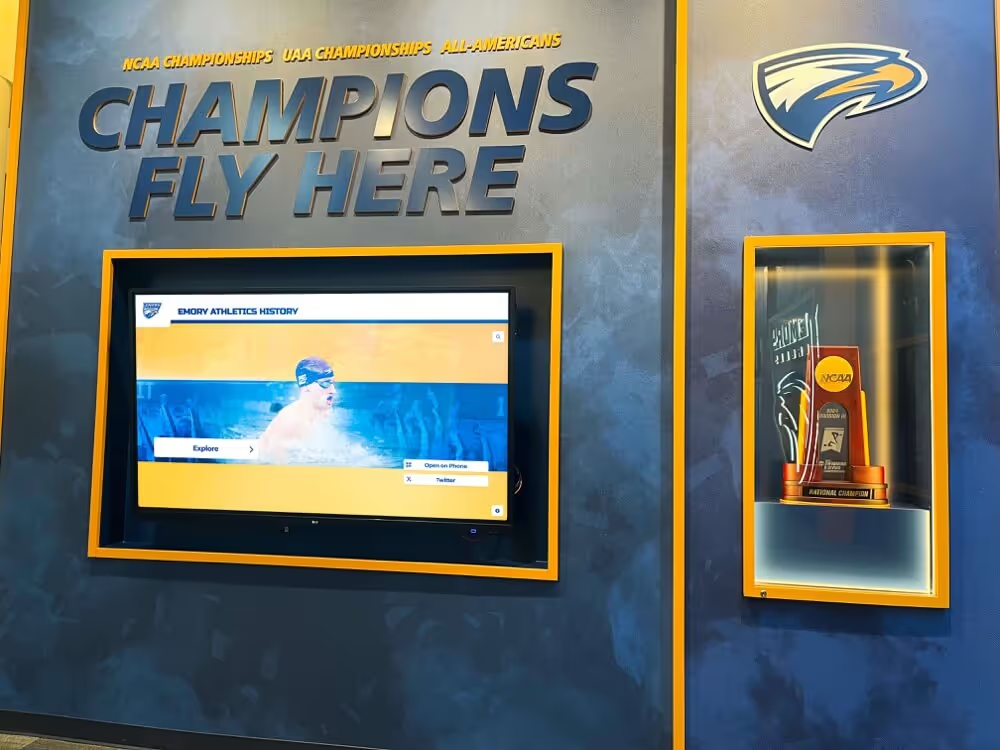
Recognition installations that begin with static photo displays often expand to include video content—validating DSC support at installation time, before video is added to the content mix, prevents reactive signal-chain troubleshooting when video is introduced
Scheduling DSC Validation Tests
When to run a full recognition display stream compression test:
- At initial installation, before the display goes live for any school audience
- After any cable replacement, extender replacement, or signal-path change
- After any GPU driver update on the source device
- After any panel firmware update
- Before any high-profile recognition event (hall-of-fame induction night, championship banner ceremony, end-of-year awards assembly) where video content will run continuously
- When any new video content type is introduced to the display content mix (particularly when video is added to an installation that previously ran only static slides)
Minimum cadence for active recognition programs:
For a recognition display operating in an athletic hallway or lobby with scheduled event-driven content updates, running the four-step artifact detection test quarterly—even when no hardware changes have occurred—catches firmware regressions and cable degradation before they produce public failures. Add the sustained load test (Step 5) annually or before any event where continuous unattended operation is expected.
Recognition programs that coordinate leadership and achievement recognition across multiple display touchpoints should apply the same per-panel validation schedule to each display, regardless of how visible or prominent that display is within the school’s recognition environment.
For IT teams responsible for data integrity and recognition record management alongside the physical display infrastructure, the DSC validation test schedule fits naturally alongside content QA reviews—both are pre-event checkpoints that protect the recognition program’s reliability.
Pre-Event Recognition Display Stream Compression Checklist
Use this checklist before any recognition event that involves high-resolution video playback on a hall-of-fame display, athletic recognition wall, or lobby kiosk.
- Confirmed GPU driver and panel firmware are both current versions (Step 1)
- Negotiated output mode verified: correct resolution, refresh rate, and DSC status confirmed in driver control panel (Step 1)
- Cable verified as correctly rated for the target interface bandwidth; length within passive cable limits or active/optical cable in use (Step 2)
- All extenders and matrix switches verified as rated for target interface and bandwidth (Step 2)
- Panel firmware version confirmed; DSC-related release notes reviewed (Step 3)
- Artifact detection test run with full motion video including fast pan content, high-contrast transitions, and on-screen text overlays (Step 4)
- No block boundary, color banding, edge halo, periodic blanking, or partial-screen corruption observed (Step 4)
- Sustained 90-minute loop test completed with no artifact onset or display reset (Step 5)
- Multi-panel installations: test completed per panel, results documented per display (Step 4, Step 5)
- Test results documented: negotiated mode, DSC status, cable model and length, firmware versions, GPU driver version, test video used, and observation notes
Frequently Asked Questions
Q: Our recognition display runs at 1080p, not 4K. Do we need to worry about DSC?
Most 1080p display installations do not require DSC—1080p at 60 Hz is well within the bandwidth available on HDMI 1.4, HDMI 2.0, and DisplayPort 1.2. DSC is primarily relevant for 4K and higher resolutions, and for 1080p at very high refresh rates (240 Hz+). If your display is operating at 1080p/60 Hz over standard HDMI 2.0 or DisplayPort 1.4, the DSC negotiation test steps are not applicable—focus instead on cable integrity and HDMI signal strength validation appropriate for your signal path length.
Q: How do I find out whether our recognition display panel supports DSC?
Check the panel’s product specification sheet, which should list the supported input modes including any DSC-dependent modes. Alternatively, connect the panel to a PC and run an EDID reading tool—the EDID extended blocks and the HDMI Forum Vendor-Specific Data Block contain the DSC capability flags. If you do not have an EDID reader available, the panel manufacturer’s technical support team can confirm whether a specific model and firmware version supports DSC and at which input modes it activates.
Q: Can DSC be used over a wireless HDMI or wireless presentation system?
Wireless HDMI and wireless presentation systems (WiGig-based systems, Wi-Fi-based casting systems) have their own compression and transmission architectures that are separate from the wired DSC specification. Some wireless systems apply their own proprietary compression independently of DSC. For recognition display installations where wireless video is used, consult the wireless system manufacturer for information on supported output modes and any codec limitations. DSC testing as described in this guide applies to wired DisplayPort and HDMI connections; wireless signal paths require different validation approaches specific to the wireless system in use.
Q: Our recognition display works fine most of the time but shows a brief black flicker during video transitions. Is this a DSC problem?
Brief black flickers during video transitions on a display with a correctly negotiated DSC mode are most commonly caused by either the media player software pausing between clips while the codec resets (a software behavior that can be adjusted in the player’s playback settings), or a bandwidth transient at the scene cut that causes the cable to momentarily drop the signal. Run the cable verification step (Step 2) with a known-good rated cable to rule out the cable as the source. If the flicker persists with a verified cable and occurs only during video content transitions rather than during continuous playback, investigate the media player’s clip transition handling and any inter-clip gap settings in the recognition platform’s playlist configuration.
Q: How is Display Stream Compression different from the video compression format (H.264, H.265) used in the video files?
These are two completely independent compression layers. Video file compression (H.264, H.265/HEVC, AV1, and similar codecs) compresses the video at the media file level—it is how the video data is stored and decoded by the media player. Display Stream Compression operates at the display interface level—it compresses the already-decoded video frame data as it is transmitted over the DisplayPort or HDMI cable from the source GPU to the display panel. A recognition system decodes an H.265 video file, sends the decoded frames to the GPU, and the GPU then applies DSC to those frames for transmission to the panel. Both compression layers are active and independent. The artifact types they produce are also different: H.265 video compression artifacts appear at high motion or low bitrate and are visible in the video file itself regardless of how it is displayed; DSC artifacts are visible only on the physical display and do not appear in the video file or on other display connections from the same source.
Ready to See a Recognition Display Built for AV Reliability?
Rocket Alumni Solutions designs interactive hall-of-fame touchscreens, athletic recognition walls, and digital donor displays with signal integrity in mind—so your installation runs high-resolution video cleanly from day one and holds up through every event in the calendar. If your school is planning or expanding a recognition display program and wants to discuss content delivery, signal chain requirements, and pre-event validation with a team that understands school AV environments, schedule a demo to see the complete system in action.
Book a Live Demo