

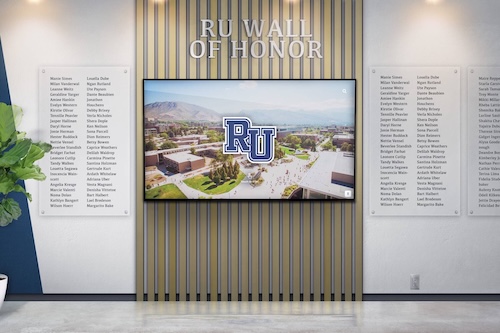
A school recognition display RSTP convergence test verifies that Rapid Spanning Tree Protocol (IEEE 802.1w) reconfigures your managed-switch topology quickly enough after an uplink failure that a lobby kiosk or hall-of-fame touchscreen reconnects to the network within seconds rather than sitting offline for half a minute or more. RSTP convergence is the process by which switches in a network with redundant paths detect a failed link, elect a new active path, and transition the relevant ports from Discarding through Learning to Forwarding—restoring normal traffic flow. When RSTP is correctly configured, convergence completes in one to six seconds. When it is misconfigured or a switch is running classic STP (802.1D) rather than RSTP, the same failover can take thirty to fifty seconds—long enough for an uplink failure during an awards ceremony or induction night to produce a visible content outage on the recognition display.
This guide walks school IT coordinators, network administrators, and facilities technology staff through the complete RSTP convergence test: confirming RSTP is active on the managed switches in the recognition display’s network path, establishing a continuous connectivity baseline before triggering a link failure, timing the failover, observing port-state transitions, and recording results in a pass/fail format that documents the display’s failover behavior for future maintenance reviews.
RSTP convergence is a background network process that is invisible when it works correctly—network traffic pauses briefly, then resumes, and the recognition display reconnects to its cloud platform without any visible interruption. It becomes visible only when it takes too long: the display shows buffering errors or cached content instead of live updates, and administrators who restart the display or investigate the network find that the switch simply needed more time to rebuild its spanning tree topology than the recognition display’s connection could tolerate.

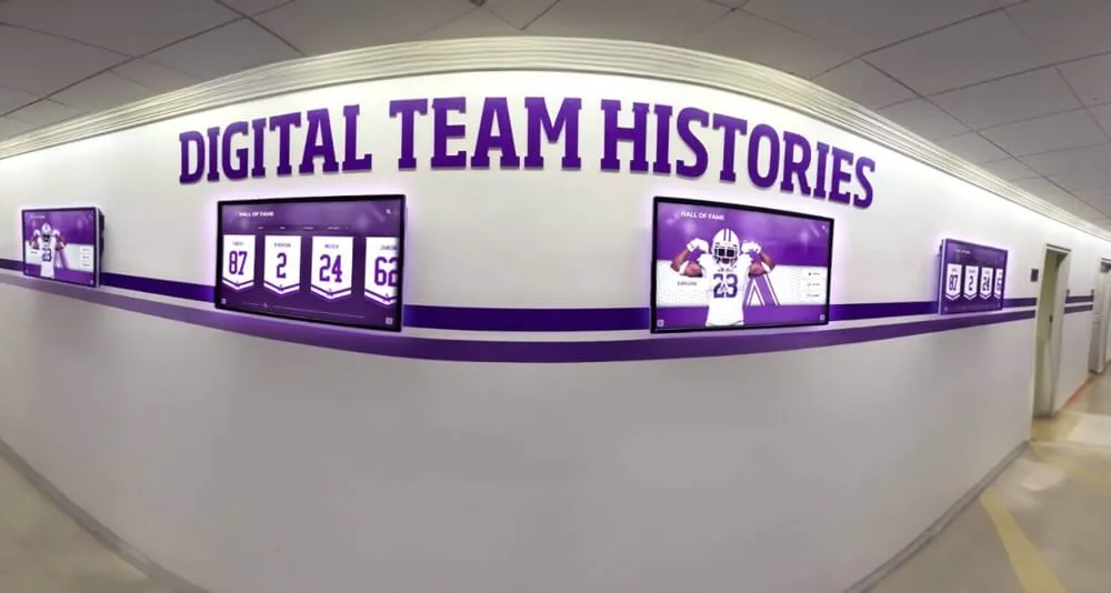
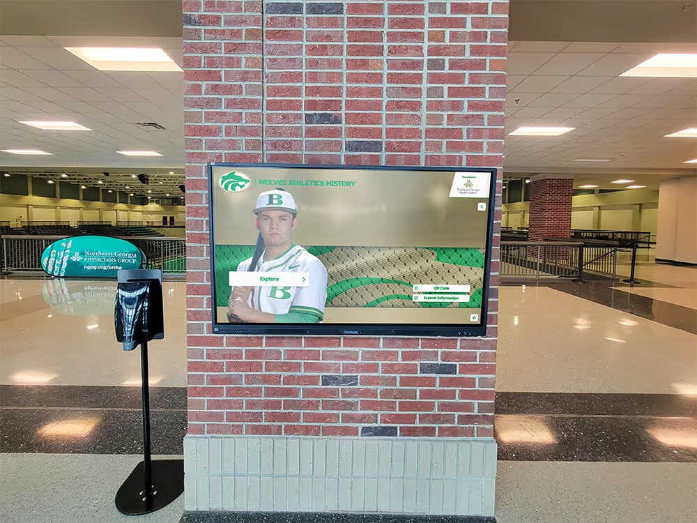
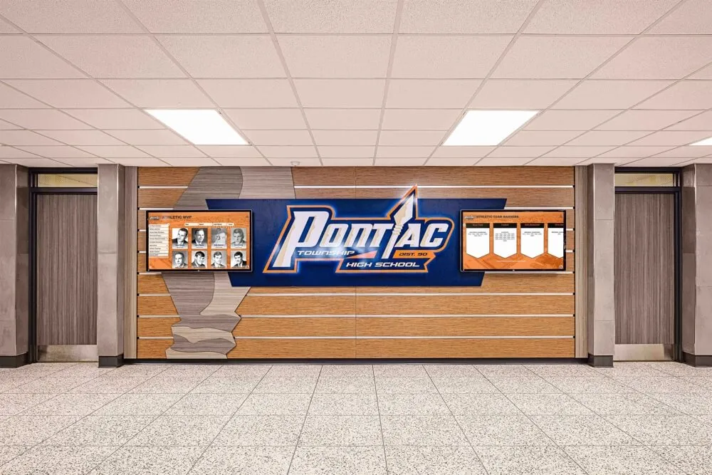
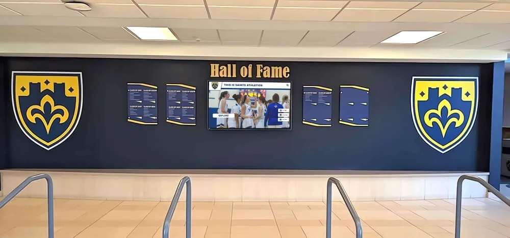
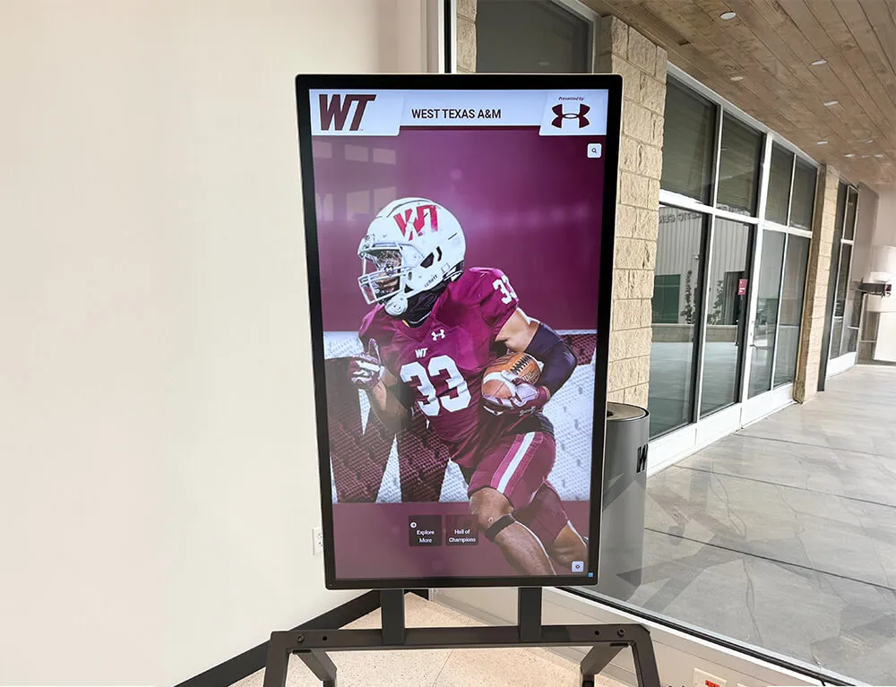
Recognition display kiosks in school athletics corridors depend on managed-switch RSTP convergence to restore network connectivity quickly after a link failure—a convergence test measures the actual failover time and confirms it meets the threshold for uninterrupted recognition content delivery
What RSTP Convergence Means for School Recognition Displays
Rapid Spanning Tree Protocol prevents network loops in environments where switches are connected by multiple physical paths. A loop—two or more paths active simultaneously between the same pair of switches—causes broadcast storms that can bring an entire network segment offline. STP and RSTP solve the loop problem by placing redundant ports into a blocking state, keeping only one active path. When the active path fails, the protocol transitions a blocking port to forwarding, restoring connectivity.
The difference between STP and RSTP is the speed of that transition. Classic STP (802.1D) uses fixed timers: a port that was blocking waits up to thirty seconds (Max Age plus Forward Delay) before it can forward traffic. RSTP (802.1w) replaces this timer-based approach with an explicit proposal-and-agreement handshake between adjacent switches, allowing ports to transition to Forwarding in one to six seconds in most school switch environments.
For recognition displays, the practical effect is straightforward.
A display connected through a managed switch with RSTP correctly configured will experience a brief interruption—typically less than five seconds—when the active uplink fails and the switch transitions the redundant uplink to Forwarding. The display’s cloud platform connection drops and then restores. Most content delivery protocols handle a sub-five-second interruption without visible degradation: the display’s player buffers ahead of playback and reconnects without showing a buffering indicator.
A display connected through a switch running classic STP, or a switch where RSTP is enabled in name but a neighboring switch is advertising STP BPDUs (causing a fallback to the slower protocol), will experience a thirty-to-fifty-second gap. Content delivery protocols typically cannot buffer across this interval. The display shows an error state, a loading screen, or frozen content—and that state is visible to anyone in the hallway or lobby during the outage window.
Recognition displays installed in school athletics hallways—carrying championship records, hall-of-fame induction profiles, and award histories for programs that recognize student achievement across academic and athletic domains—need the network infrastructure beneath them to recover from link failures at RSTP speed, not STP speed.
RSTP Port States and Convergence Timing
RSTP reduces the number of port states from the five states in classic STP (Disabled, Blocking, Listening, Learning, Forwarding) to three (Discarding, Learning, Forwarding). Understanding these states is useful when reading the output of switch diagnostic commands during the test.
| RSTP Port State | What the Port Does | Typical Duration |
|---|---|---|
| Discarding | Drops all data frames; processes BPDUs only | Maintained on blocking ports; brief transition during failover |
| Learning | Processes BPDUs; builds MAC address table; does not forward data | 0–15 seconds (often bypassed via proposal/agreement) |
| Forwarding | Fully operational; forwards data frames normally | Maintained on active ports |
| RSTP Port Role | Description |
|---|---|
| Root Port | The port on a non-root switch with the lowest-cost path to the root bridge |
| Designated Port | The forwarding port on a network segment providing the best path to the root |
| Alternate Port | A blocked port providing an alternate path to the root; transitions to Root Port when the current Root Port fails |
| Backup Port | A blocked port providing a backup to the same segment as another Designated Port on the same switch |
When the active uplink (Root Port) on the switch serving the recognition display fails, the Alternate Port transitions from Discarding to Forwarding. With RSTP and correct configuration, this transition skips the Learning state via the proposal/agreement mechanism and completes in one to three seconds. With classic STP, or when the proposal/agreement mechanism is blocked by a misconfiguration, the port progresses through all states with fixed timers—taking thirty seconds or more.
Pre-Test Preparation Checklist
Complete every item before starting the convergence test. The test involves intentionally disconnecting an uplink cable or disabling a switch port, which causes a brief network interruption on the tested segment. Do not perform the test during normal school hours without notifying staff whose devices share the same VLAN.
Topology Mapping
- Identify all managed switches in the network path between the recognition display and the distribution or core layer
- Identify the active uplink (Root Port) on the switch directly serving the recognition display
- Confirm a redundant uplink exists on that switch—either a second physical uplink to a different upstream switch, or a second port in an active ring topology
- Confirm the redundant uplink is currently in Discarding or Alternate state (not in Forwarding—if both ports are forwarding, spanning tree is not operating correctly)
- Diagram the physical path: recognition display → access switch → uplink → distribution switch (or equivalent for your topology)
Switch Access
- Confirm SSH or console access to the switch directly serving the recognition display
- Confirm SSH or console access to the upstream distribution switch (needed to verify topology from the upstream perspective)
- Confirm your account has read access to
showcommands on each switch (read-only access is sufficient for the baseline; write access may be needed if RSTP configuration corrections are required)
RSTP Configuration Baseline
- Confirm RSTP (802.1w) or MSTP (802.1s, which includes RSTP behavior) is enabled on the recognition display VLAN across all switches in the path—not classic STP (802.1D)
- Confirm PortFast (or equivalent Edge Port) is enabled on the switch port serving the recognition display—PortFast allows the display’s port to transition immediately to Forwarding on link-up without waiting for spanning tree timers, which is correct for edge ports that connect to end devices, not other switches
- Confirm BPDU Guard is enabled on the recognition display port—a related spanning tree control that protects the display’s access port from accidentally receiving BPDUs that could trigger unnecessary topology changes (see the recognition display BPDU guard test for a full verification procedure)
Test Environment
- Monitoring laptop connected to the same network segment as the recognition display (wired preferred)
- Continuous ping running from the monitoring laptop to the recognition display’s IP address before the test begins
- Access to the recognition display’s administrative console or content platform sync status to confirm cloud connectivity
- Stopwatch or timestamp-capable logging tool to measure the convergence interval
- Maintenance window approved with IT leadership; recognition program staff notified that network connectivity to the display will be briefly interrupted during the test
Coordination
- Confirm recognition content is current on the display before starting—so the content state before and after the test is directly comparable
- Confirm the test uplink cable is physically accessible (labeled and reachable at the switch panel or rack)
- If the test involves disabling a port via CLI rather than unplugging a cable, confirm the port number and the command syntax for your switch platform before starting
Recognition Display RSTP Convergence Test: Numbered Procedure
Run each step in sequence. Record timestamps at each step; the convergence interval is measured between the moment the uplink fails and the moment the continuous ping to the recognition display resumes successfully.
Step 1 — Verify RSTP is enabled on the recognition display VLAN
On the switch directly serving the recognition display, confirm RSTP (or MSTP) is the active spanning tree mode, not classic STP.
On Cisco IOS / IOS-XE:
show spanning-tree vlan <vlan-id>
In the output, confirm:
- Spanning tree enabled protocol shows
rstporieee(for 802.1w)—notstp(classic 802.1D) - Root ID and Bridge ID sections show correct priority values
- The port connecting to the uplink switch shows Role of
RootorAltn(Alternate), and State ofFWD(Forwarding) orBLK(Blocking/Discarding)
On Ubiquiti UniFi: navigate to Devices > select the switch > Ports > confirm Spanning Tree is set to RSTP, not STP, in the switch’s port profile or network settings.
On Netgear ProSAFE: navigate to Switching > Spanning Tree > STP Configuration and confirm the STP Version is set to RSTP or MSTP.
If any switch in the path is running classic STP, the test will confirm slow convergence—and the finding will require changing the spanning tree mode to RSTP before the test can pass.
Document the spanning tree mode and current port states for the uplink and the redundant alternate port.
Step 2 — Confirm the Alternate Port is in Discarding state
Identify the redundant uplink port on the access switch serving the recognition display. This port should currently be in the Discarding (blocked) state, ready to transition to Forwarding when the active Root Port fails.
On Cisco IOS / IOS-XE:
show spanning-tree vlan <vlan-id> detail
Locate the port that is currently in BLK (Blocking/Discarding) state with a Role of Altn. Document:
- Interface name of the Alternate Port
- Current state:
BLKorDiscarding - Cost and priority values
- The upstream switch and port it connects to
If no Alternate Port exists in Discarding state, the switch has no redundant path—there is nothing to fail over to, and the RSTP convergence test will measure only the reconnection time after the link is manually restored, not a true RSTP failover. Confirm with your topology documentation whether a redundant uplink was planned for this switch. If not, the test outcome documents that the recognition display’s switch has no redundant path and is dependent on a single uplink.
Step 3 — Establish the continuous ping baseline
From the monitoring laptop, begin a continuous ping to the recognition display’s IP address. This ping will be the primary measurement tool: the interval between the last successful ping before the link failure and the first successful ping after the link is restored via RSTP failover is the convergence interval.
On Windows:
ping <recognition-display-ip> -t
On Linux/macOS:
ping <recognition-display-ip>
Confirm that the ping is receiving successful replies before proceeding. Note the average round-trip time; a significant increase in RTT after failover (without packet loss) can indicate the new path has higher latency—a secondary finding worth documenting.
Step 4 — Log the current time and trigger the uplink failure
Record the exact timestamp before triggering the link failure. This is the start of the convergence interval.
Trigger the failure using one of two methods:
Method A — Physical disconnection: Unplug the uplink cable from the active Root Port on the access switch serving the recognition display. This is the most realistic simulation of a physical link failure.
Method B — Administrative shutdown: If physical cable access is constrained, shut down the active uplink port via CLI:
On Cisco IOS / IOS-XE:
interface GigabitEthernet0/X
 shutdown
Replace GigabitEthernet0/X with the actual interface of the active Root Port. This immediately brings the link down without requiring physical access to the cable.
Note the exact time of the failure trigger in your test log.
Step 5 — Observe ping behavior and measure the convergence interval
Watch the continuous ping output. Count the number of consecutive ping timeouts after the link failure. Each timeout represents one second (default ping interval) during which the recognition display is not reachable.
When the ping resumes—when successful replies begin appearing again—note the exact time. The convergence interval is the elapsed time between the failure trigger (Step 4) and the first successful ping reply after failover.
Simultaneously, on the switch CLI (in a separate SSH session), observe the spanning tree port state transition:
show spanning-tree vlan <vlan-id>
Refresh this command every second to observe the Alternate Port transitioning from BLK to FWD. On Cisco switches, you can also watch the spanning tree topology change log:
show spanning-tree vlan <vlan-id> detail | include Topology
Document:
- Number of ping timeouts (each = ~1 second)
- Total convergence interval in seconds
- Port state of the Alternate Port before and after failover (
BLK→FWD) - Whether a topology change notification was logged by the switch
A convergence interval under five seconds is a pass for RSTP. A convergence interval of fifteen to fifty seconds indicates classic STP behavior or a misconfiguration causing RSTP to fall back to timer-based convergence. A convergence interval over fifty seconds indicates a serious spanning tree misconfiguration requiring investigation before the display can be considered reliably protected against link failures.
Step 6 — Verify the recognition display reconnected to the cloud platform
After the ping resumes, navigate to the recognition display’s administrative console or content platform sync interface and confirm:
- The cloud platform connection is active (sync status shows a recent heartbeat)
- Content updates are flowing normally
- The display is showing current content, not frozen or cached content from before the failover
If the display remains on an error screen even after the ping resumes—meaning RSTP restored network connectivity but the application layer has not recovered—document this as a separate finding. Some display platforms require longer to re-establish their cloud connection after a network interruption than the RSTP convergence interval itself. If recovery takes more than thirty seconds after ping success, investigate whether the content platform has a reconnection backoff timer that can be shortened.
Schools whose recognition displays carry alumni spotlight content and graduate profiles that update on a defined schedule need the cloud platform reconnection to complete quickly after an RSTP failover—so the display is current by the time the first visitor arrives after the link interruption.
Step 7 — Restore the original link and verify topology recovery
Restore the failed uplink by reconnecting the cable (Method A) or re-enabling the port (Method B):
On Cisco IOS / IOS-XE:
interface GigabitEthernet0/X
 no shutdown
After restoring the link, observe the spanning tree state on both the restored port and the current Root Port. With RSTP, the switch may elect the original port as the new Root Port if it has a better cost or priority than the port that took over during failover. This reconvergence (the original path being restored and the failover path returning to Discarding) is a second RSTP convergence event.
Time this second convergence interval as well. Document:
- Time from link restoration to spanning tree reconvergence
- Final port states: which port is Root Port, which is Alternate
- Whether the ping showed any interruption during reconvergence (for RSTP, reconvergence should also complete quickly and the ping may show zero timeouts if the switch handles the transition smoothly)
Step 8 — Repeat the test with the alternate uplink
To fully characterize the recognition display’s failover resilience, repeat the test by triggering a failure of the alternate uplink path (the one that became the Root Port during Step 5). This test confirms that failover works in both directions—that the display remains protected whether the original uplink or the backup uplink fails.
Repeat Steps 4 through 6 with the alternate uplink disconnected or shut down. Document the second convergence interval. Both intervals should be under five seconds for a complete RSTP pass.
If the second convergence interval significantly exceeds the first, the two uplinks have different RSTP configurations—different port costs, priorities, or neighboring switch configurations—that cause asymmetric failover behavior. Document the difference and investigate whether the uplink costs and priorities are set intentionally or by default.
Step 9 — Test failover under active content load
Repeat the uplink failure (Step 4) while the recognition display is actively streaming a video segment or refreshing a content update cycle. This tests whether the display’s content platform handles the RSTP convergence interval cleanly under load, not only during idle periods.
Observe:
- Whether the video stalls or shows a buffering indicator during the convergence interval
- Whether the content recovers automatically after ping resumes, without requiring a manual display restart
- Whether the convergence interval under load differs from the idle convergence interval (it should not differ significantly—RSTP convergence is a switch-level operation independent of the application traffic level)
Document the content platform’s behavior during the convergence interval. A platform that recovers automatically is preferable to one that requires manual intervention after every link interruption.
Step 10 — Document and restore the test environment
Confirm that all switch port configurations are returned to their pre-test state. If administrative shutdown (Method B) was used, verify the port is re-enabled and fully operational.
Record the complete test findings:
- Switch platform and RSTP mode confirmed
- Active Root Port and Alternate Port identification
- Convergence interval for each failover tested (seconds and ping timeout count)
- Content platform reconnection time after RSTP convergence
- Any configuration findings (classic STP mode on any switch, missing Alternate Port, asymmetric port costs)
- Date, technician name, and maintenance window
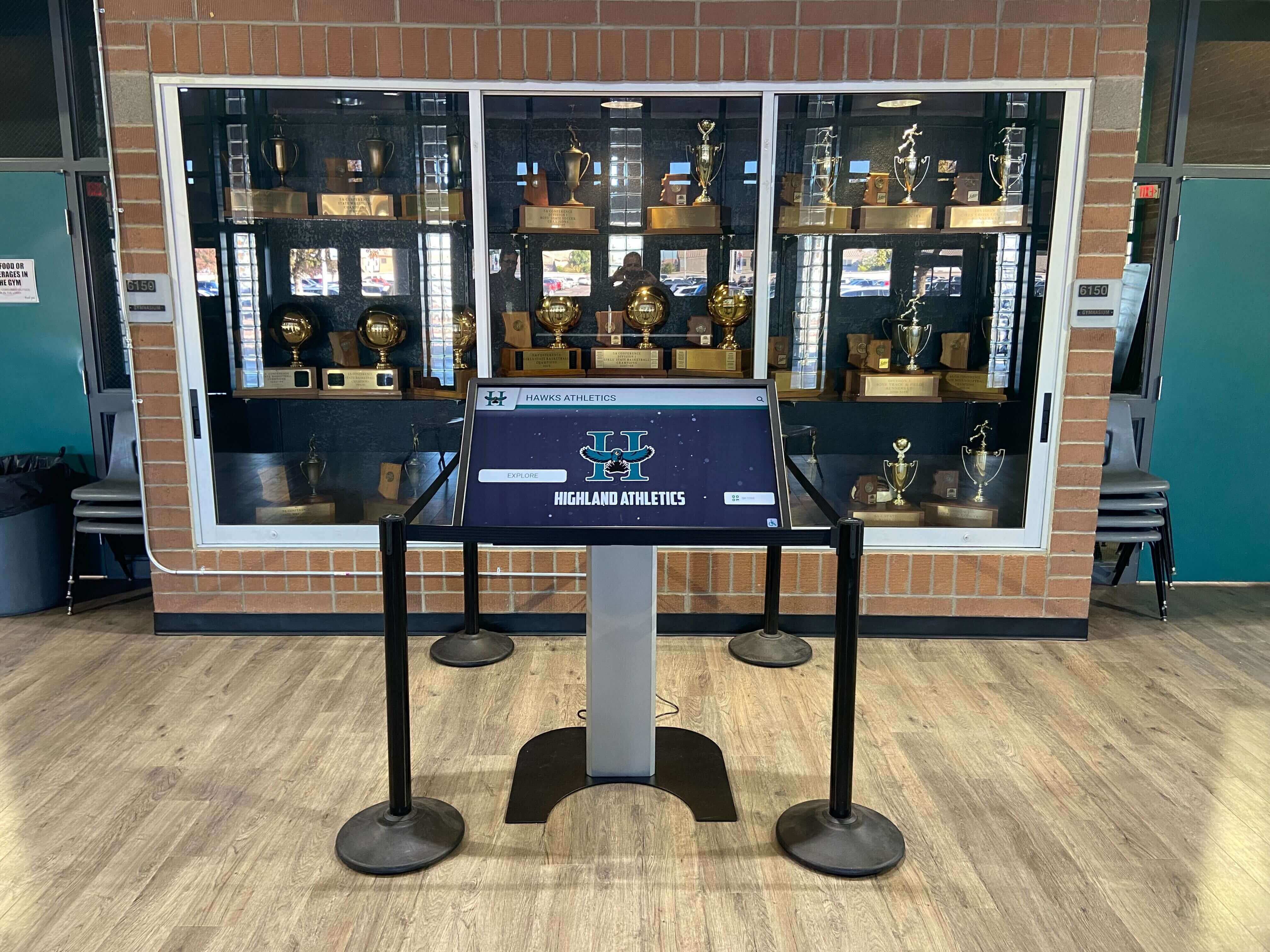
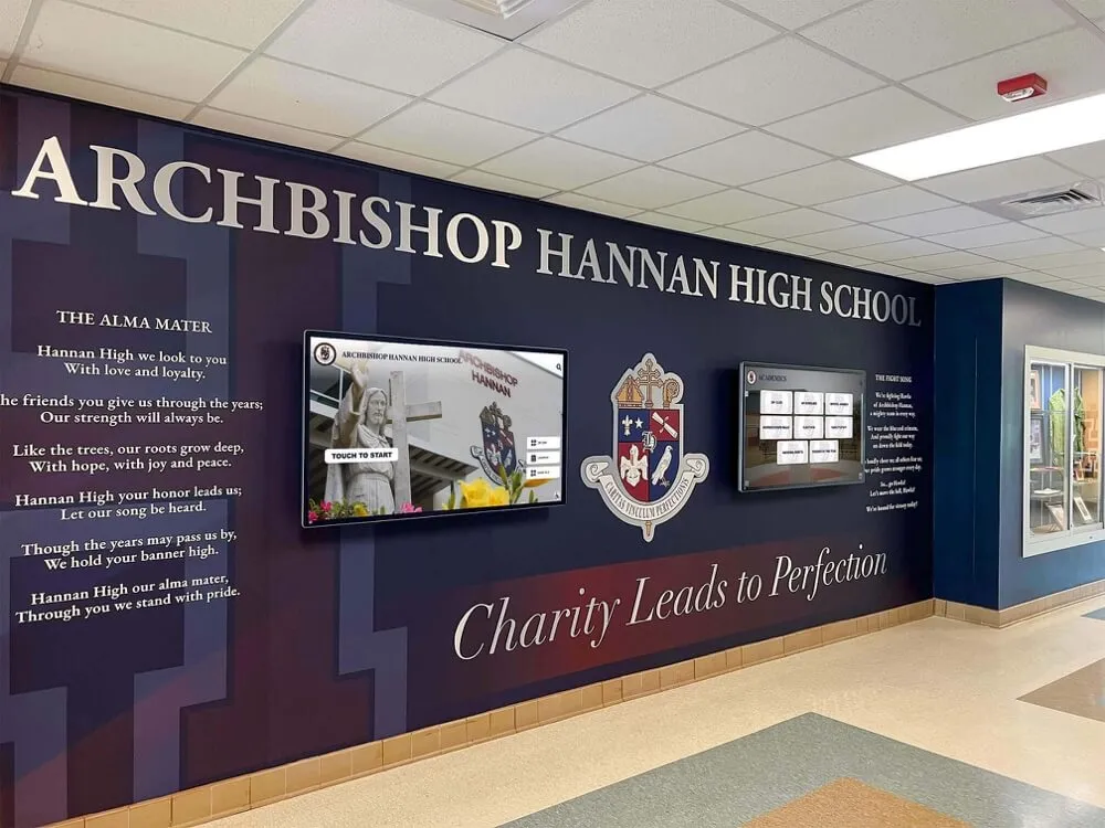
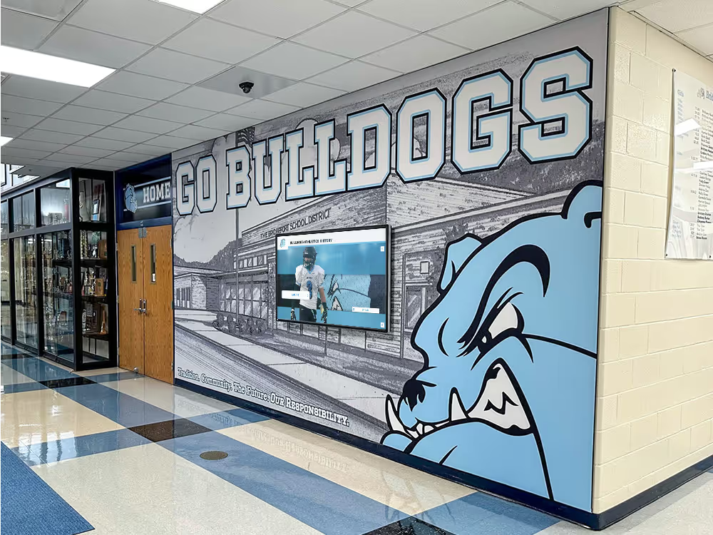
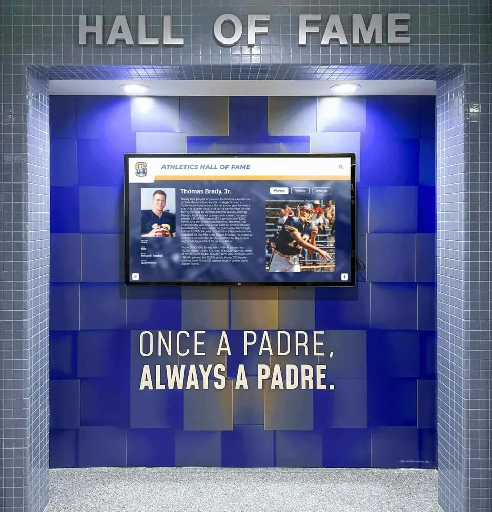
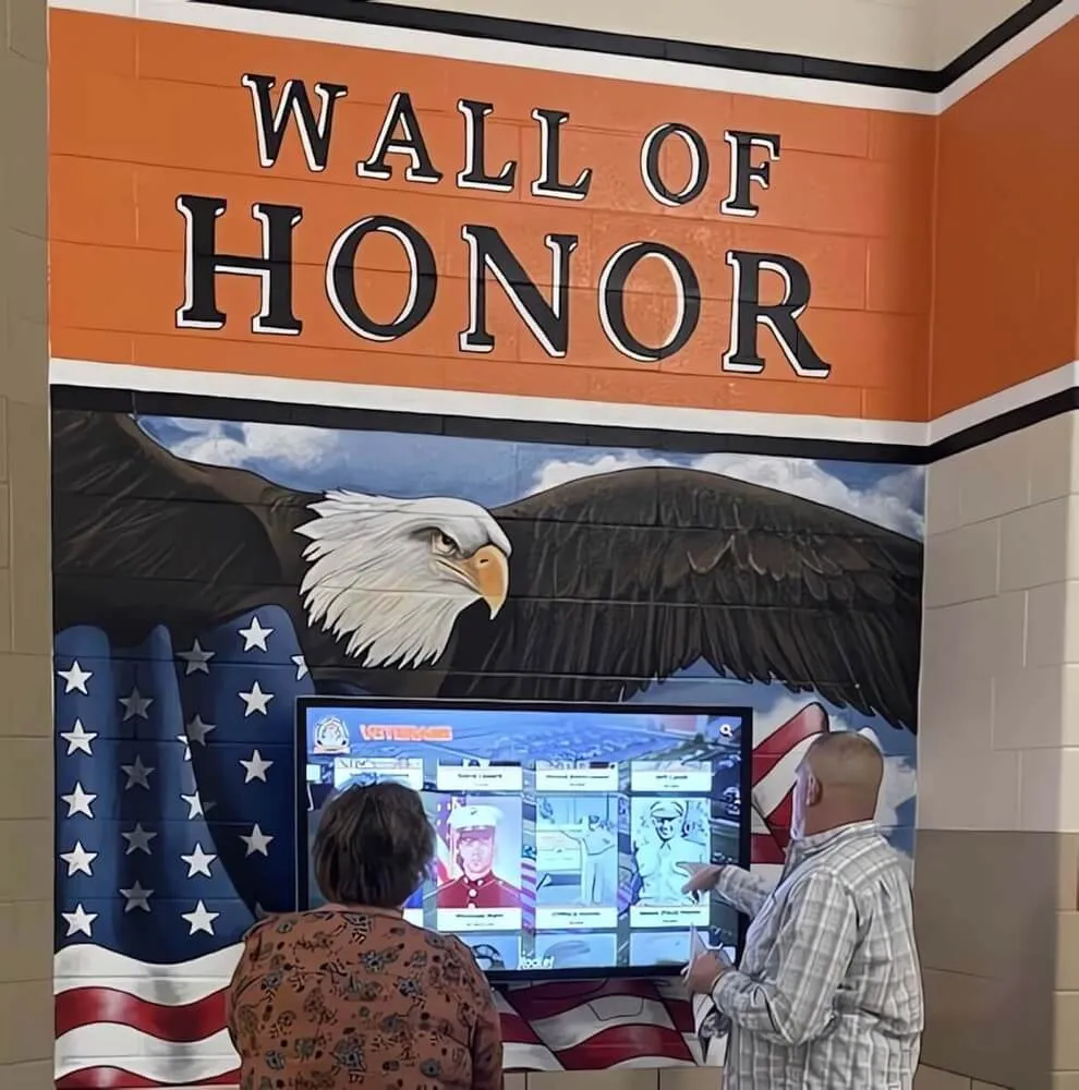
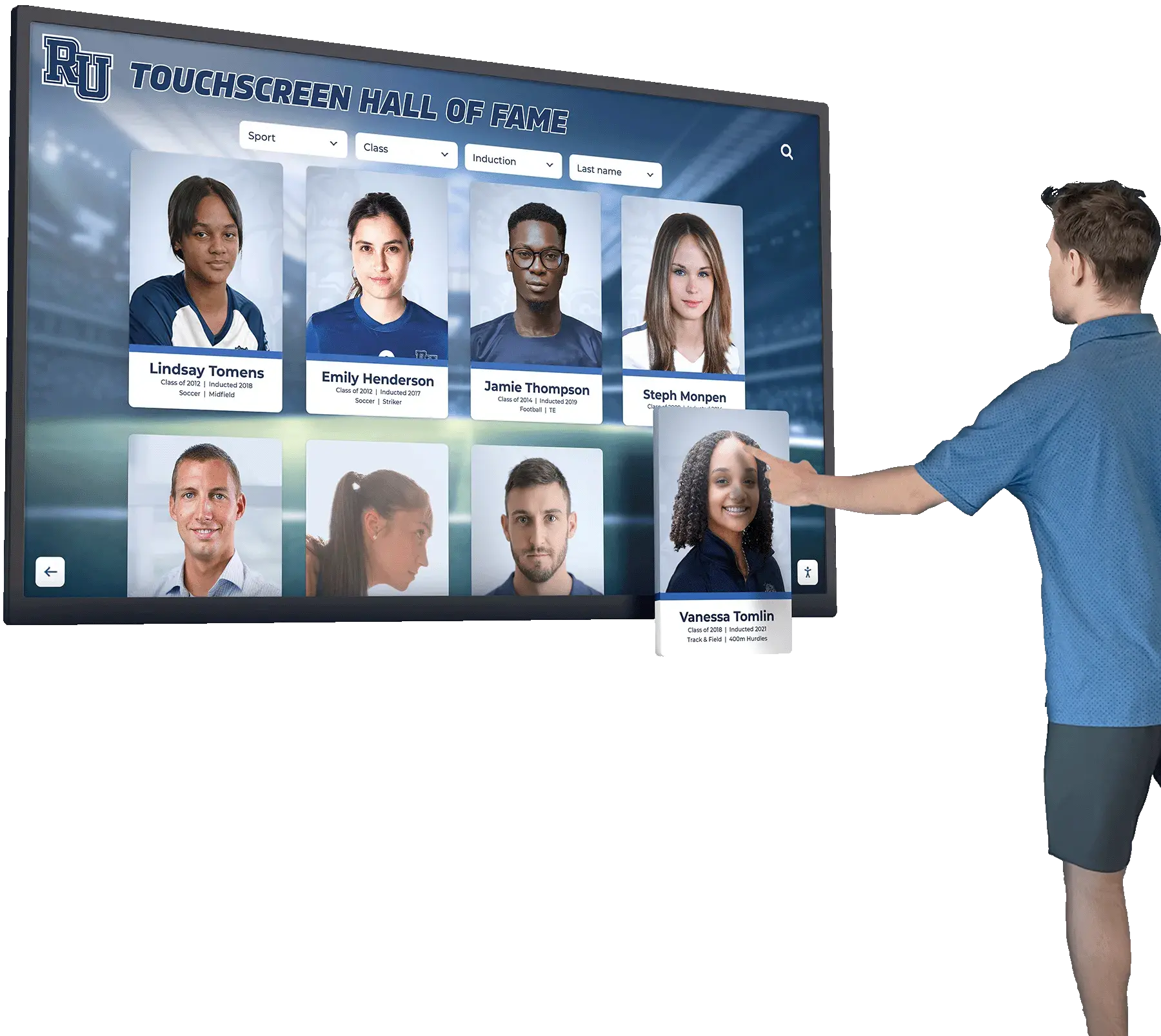
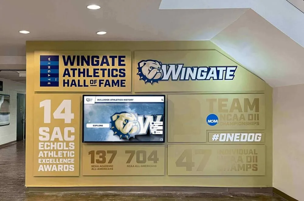
Recognition display kiosks installed in trophy cases and enclosed hallway alcoves depend on the managed-switch spanning tree protocol to restore network connectivity quickly after a link failure—an RSTP convergence test measures that recovery time and confirms it is fast enough that content delivery is not visibly interrupted
Pass/Fail Table: Interpreting RSTP Convergence Test Results
| Finding | What It Means | Recommended Action |
|---|---|---|
| Convergence interval ≤ 5 seconds, ping resumes quickly | RSTP is active and the proposal/agreement handshake is completing successfully | Document as pass; schedule next test 6 months out or before major events |
| Convergence interval 6–15 seconds | RSTP may be active but the proposal/agreement mechanism is not completing at full speed; possible STP compatibility mode or incorrect edge port configuration | Investigate whether a neighboring switch is advertising STP BPDUs; verify RSTP is enabled on all switches in the path |
| Convergence interval 15–50 seconds | Switch is running classic STP (802.1D) or has fallen back to STP compatibility mode; Forward Delay timers are controlling the transition | Enable RSTP on all switches in the path; verify no switch in the path is configured for STP-only mode |
| Convergence interval > 50 seconds | Severe spanning tree misconfiguration; possible STP loop detection false positive, incorrect Max Age, or root bridge election problem | Conduct a full spanning tree audit of the network segment before re-testing |
| No convergence observed (display remains offline) | No redundant uplink is available on the access switch, or the redundant uplink is also non-functional | Verify physical cable connectivity of the redundant uplink; if no redundant path exists, document as topology gap |
| Convergence fast but content does not recover | Network layer reconnected but application layer reconnection is slow | Investigate content platform reconnection backoff settings; consider a watchdog restart mechanism on the display player |
| Asymmetric convergence intervals (one direction fast, other slow) | Port costs or priorities differ between the two uplinks | Review spanning tree port cost and priority assignments on both uplink ports; equalize if asymmetry is unintentional |
| Reconvergence (link restoration) causes a second interruption | Normal RSTP behavior when the original Root Port is restored | Verify the reconvergence interval is also under 5 seconds; if the display requires continuity during link restoration, consider configuring the failover path as the permanent Root Port |
Timed Failover Reference: Expected Convergence Intervals by Configuration
Use this table to set expectations before testing and to interpret findings afterward.
| Spanning Tree Configuration | Expected Convergence Interval | Recognition Display Impact |
|---|---|---|
| RSTP (802.1w), edge port with PortFast on display port | 1–3 seconds | Ping shows 1–3 timeouts; content platform typically recovers without visible disruption |
| RSTP (802.1w), no PortFast on display port | 1–5 seconds | Slightly longer if the display port itself must re-negotiate; still within acceptable range |
| RSTP with one classic STP switch in path | 15–30 seconds | Classic STP switch forces STP compatibility mode on adjacent RSTP switches; display shows visible content outage |
| Classic STP (802.1D) throughout | 30–50 seconds | Full Forward Delay timers apply; display shows error state for thirty or more seconds |
| RSTP with mismatched priorities or costs | Variable (5–30 seconds) | Convergence time depends on which incorrect values apply; asymmetric behavior common |
| RSTP, no redundant uplink | N/A (no failover path) | Display remains offline until the failed link is physically restored; convergence is not the constraint |
Switch Platform Configuration Reference
The commands for verifying and configuring RSTP vary by platform. Use this table to locate the relevant settings for your switch environment.
| Platform | Enable RSTP | Verify RSTP Mode | Show Port States |
|---|---|---|---|
| Cisco IOS / IOS-XE | spanning-tree mode rapid-pvst | show spanning-tree vlan <id> | show spanning-tree vlan <id> detail |
| Cisco Meraki | Dashboard: Switch > Spanning Tree > RSTP | Dashboard: Switch > STP settings per network | Dashboard: Switch > Ports > STP status |
| Ubiquiti UniFi | Network app: Settings > Networks > select network > Spanning Tree > RSTP | Network app: Devices > Switch > Ports > STP column | Network app: Devices > Switch > Statistics |
| Netgear ProSAFE | Web GUI: Switching > Spanning Tree > STP Configuration > Mode: RSTP | Web GUI: Switching > Spanning Tree > STP Status | Web GUI: Switching > Spanning Tree > Port Status |
| HPE Aruba / AOS | spanning-tree (RSTP is default on modern AOS) | show spanning-tree | show spanning-tree ports detail |
| TP-Link JetStream | Web GUI: L2 Features > Spanning Tree > RSTP | Web GUI: L2 Features > Spanning Tree > STP Summary | Web GUI: L2 Features > Spanning Tree > Port Config |
For any platform not listed, the key verification commands are equivalent: confirm the global spanning tree mode is RSTP or MSTP (not STP/802.1D), and confirm the port role and state of the uplink and alternate ports on the switch serving the recognition display.
See How a Recognition Display Handles Network Infrastructure Questions
If your school is planning or expanding a touchscreen recognition display deployment and wants to walk through the network requirements—RSTP configuration, VLAN design, switch platform compatibility, and failover behavior—a live product demonstration can answer those questions for your IT team and athletic director in one session. Request a free demo from Rocket Alumni Solutions to see the platform in action and discuss the network integration your facilities team needs.
School-Specific RSTP Scenarios
School network environments create RSTP conditions that differ from corporate deployments. Understanding these scenarios helps configure and test RSTP in ways that match the actual failure modes the recognition display is most likely to encounter.
Event-Night Equipment Connections
Athletic departments and event staff routinely connect additional switches, wireless access points, and audiovisual equipment to existing network ports during championship events, induction nights, and alumni weekends. If this equipment is connected to ports that do not have PortFast or BPDU Guard enabled, a spanning tree BPDU arriving on that port can trigger a topology change—causing an RSTP reconfiguration even without a physical link failure.
Schools that run recognition content during high-profile events—displaying Gatorade Player of the Year nominees and award histories alongside championship records and hall-of-fame induction lists—should verify that all access ports in the venue are PortFast-enabled with BPDU Guard, so that a connected AV switch or temporary access point cannot trigger an unintended RSTP topology change during the event itself.
Multi-Building Ring Topologies
Many school campuses connect buildings through fiber rings—a topology where each building switch connects upstream to two different intermediate distribution switches, forming a ring. RSTP manages this ring by blocking one uplink on each switch (the Alternate Port), creating a tree topology without loops.
When one link in the ring fails, RSTP must reconfigure the blocked ports across multiple switches in the ring simultaneously. In a three-building ring, this involves coordinated proposal/agreement exchanges across potentially four or five switches. The convergence interval in a ring topology is typically longer than in a simple hub-and-spoke topology and depends on the number of switches and their STP priority configuration. Run the RSTP convergence test on the switch nearest the recognition display within the ring to measure the actual interval, not a theoretical estimate.
PoE Switch Replacements
Many school IT upgrades involve replacing older unmanaged or PoE switches with managed alternatives to support VLAN segmentation or RSTP. During a switch replacement, the replacement switch may come from the factory configured for STP compatibility mode rather than RSTP—a default that varies by vendor. If the replacement switch is inserted into a ring or redundant topology where the other switches are running RSTP, the replacement switch’s STP compatibility mode can cause every adjacent RSTP switch to fall back to STP timer-based convergence on the affected VLANs.
Run the RSTP convergence test after any switch replacement in the recognition display’s network path to confirm the replacement hardware is configured for RSTP and has not introduced classic STP behavior into the topology.
Schools that invest in recognition programs covering historical achievement displays and athletic legacy content depend on network infrastructure that remains reliable through hardware refresh cycles—RSTP convergence testing after each switch replacement is the verification step that confirms the infrastructure upgrade did not introduce a regression.
Stacked Switches and Chassis Platforms
Some school distribution switches use stacking (multiple physical switches presenting as a single logical unit) or chassis-based platforms. Within a stack or chassis, RSTP topology changes are handled by the stack master or supervisor module—failover to a backup supervisor involves a separate process (non-stop forwarding or graceful restart) that is distinct from RSTP convergence. Test RSTP convergence at the access layer (the switch directly serving the recognition display) rather than at the stacking layer. Failover within the stack itself is a separate diagnostic.
Connecting This Test to Other Display Network Diagnostics
An RSTP convergence test validates the spanning tree layer of the recognition display’s network resilience—ensuring that a topology change completes quickly enough that the display does not experience a prolonged outage. It is one part of a broader network verification practice for recognition display deployments.
Schools managing recognition displays that have grown to include both athletics and academic honors—covering programs like distinguished alumni recognition and golf team legacy content—often have recognition displays installed across multiple buildings and network segments, each with its own uplink redundancy and spanning tree topology. Running RSTP convergence tests at each segment individually confirms that every display has documented failover behavior before a major recognition event.
Displays that have been verified for RSTP convergence and also confirmed for BPDU guard behavior—ensuring that spanning tree topology changes are not accidentally triggered by connected AV equipment—have the two most common spanning tree failure modes covered. Schools managing digital hall of fame platform audits and network topology reviews can use RSTP convergence test findings as the spanning tree section of a broader network verification report.
Schools whose recognition programs serve content through locker room displays and athletics facility panels—spaces where network cabling and switch connectivity may be subject to physical disruption during facility use—can cross-reference the locker room design and functional planning considerations that inform how network infrastructure is routed and protected within those spaces. Physical cable protection reduces the frequency of link failures; RSTP convergence testing validates the recovery when a failure occurs despite that protection.

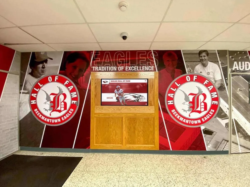
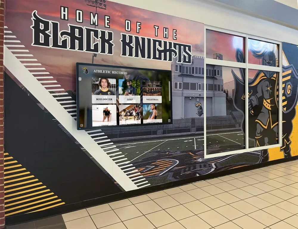
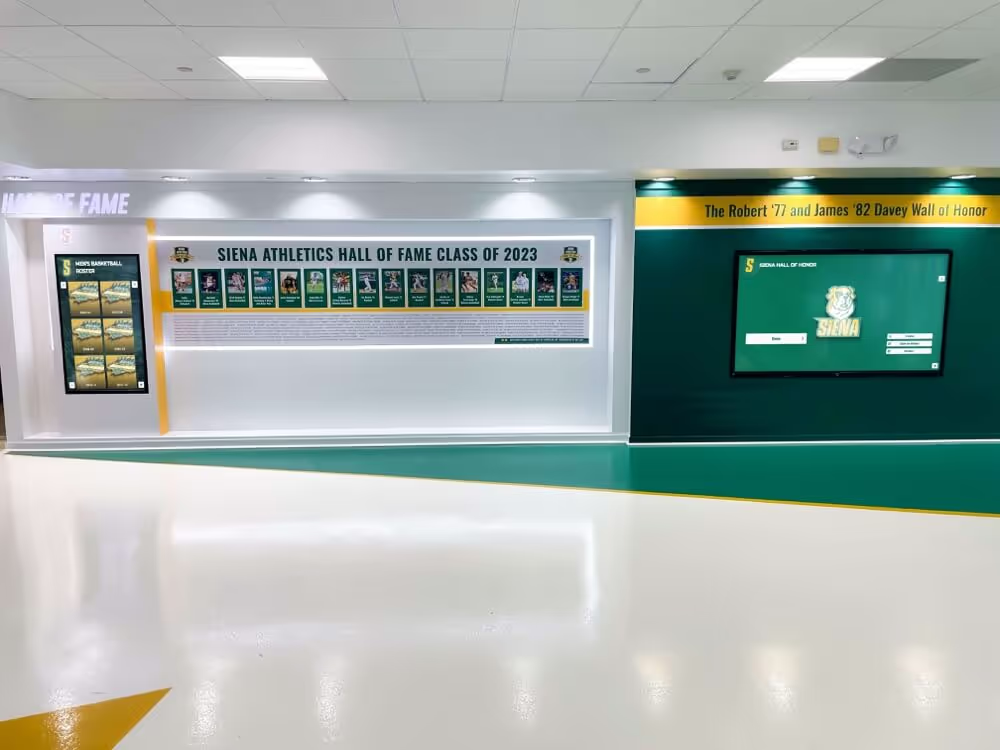
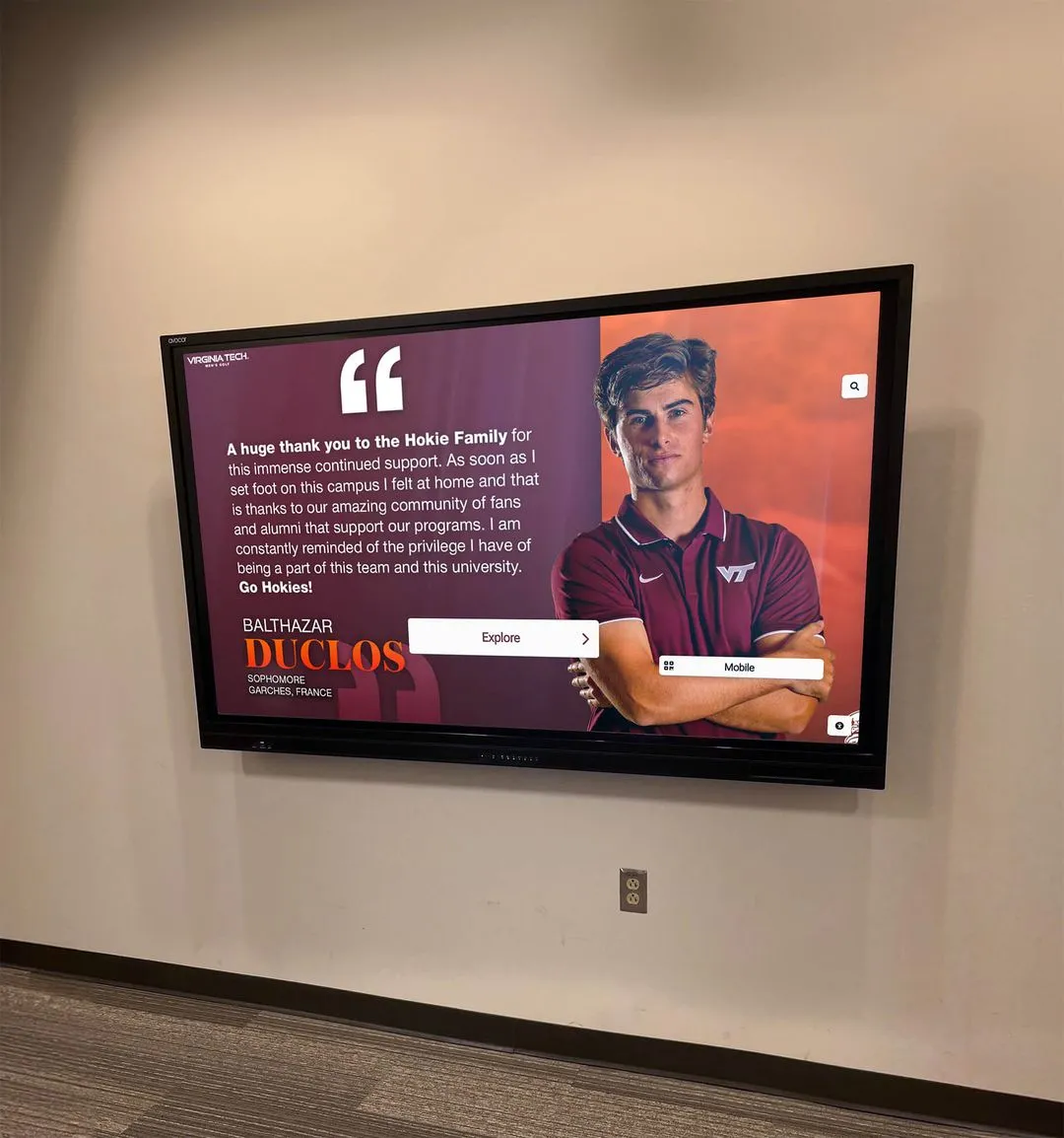
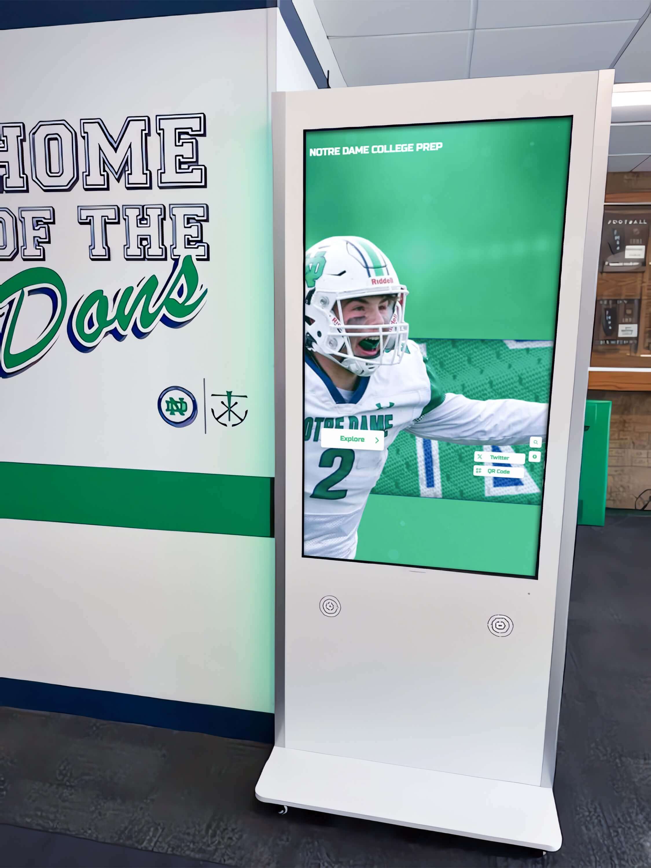
Athletics hallway recognition displays are most visible—and network uplink failures are most disruptive—during the events these displays are designed to celebrate; RSTP convergence testing confirms the switching infrastructure recovers fast enough to keep the display running without a visible interruption
Q&A: RSTP Convergence and Recognition Display Failover
How does RSTP convergence time differ from reconnection time on the recognition display itself?
RSTP convergence is a switch-level process: it measures how quickly the switches reconfigure their port states after a link failure, restoring the Layer 2 path between the recognition display and the rest of the network. Reconnection time is the additional time required for the display’s operating system and content platform to re-establish TCP connections, authenticate to the cloud platform, and resume content delivery after the network path is restored. In a well-configured environment, RSTP convergence completes in one to five seconds, and the display’s application layer reconnects within another five to fifteen seconds. The RSTP convergence test measures the network-layer interval; post-convergence application recovery is a separate measurement.
Our school has RSTP enabled but convergence is still taking fifteen to twenty seconds. What causes this?
The most common cause is that one or more switches in the network path is running classic STP (802.1D) rather than RSTP. When an RSTP switch receives BPDUs from an adjacent classic STP switch, it falls back to STP behavior on that port—even though RSTP is enabled globally. Identify every switch between the recognition display and the distribution layer and verify that RSTP is enabled on each. A second common cause is that the Alternate Port is not in a true Alternate state: if the switch treats the redundant uplink as a Designated Port on the same segment, RSTP cannot use the fast proposal/agreement mechanism, and the port must progress through the Learning state with a fifteen-second Forward Delay timer.
Should PortFast be enabled on the recognition display’s access port?
Yes. PortFast (or the equivalent Edge Port setting on non-Cisco platforms) tells the switch that the port connects to an end device—not another switch—and allows the port to transition directly to Forwarding when the display powers on or reconnects, without waiting for spanning tree negotiation. PortFast does not affect uplink failover behavior; it affects how quickly the display’s own port recovers after the display is powered on or reconnected following an outage. Always pair PortFast with BPDU Guard on the display port, which will disable the port if it receives a BPDU—protecting against an accidental switch connection to the display port.
What if the recognition display’s switch has only a single uplink and no redundant path?
If there is no redundant uplink, there is no Alternate Port to fail over to. The RSTP convergence test will confirm this: when the single uplink fails, the display remains offline until the physical cable is restored, regardless of RSTP configuration. The RSTP convergence test result in this scenario is a topology finding, not a configuration finding: the switch has no redundant path, which is the root cause of potential extended outages. Adding a second uplink to a different upstream switch is the infrastructure change required to make RSTP failover possible. Document the finding and include it in any upcoming network infrastructure review for the facilities serving the recognition display.
How often should the RSTP convergence test be run?
Run the test twice per year for managed switch networks with redundant uplinks: once before fall athletics season and once before spring awards and graduation events. Additionally, run the test after any topology change in the recognition display’s network path: switch replacement, uplink recabling, VLAN restructuring, or any firmware update to the switches in the path. RSTP behavior after firmware updates occasionally changes if the update modifies the spanning tree implementation or default configuration values.
Can the RSTP convergence test disrupt devices other than the recognition display?
Yes, if the tested switch serves other devices on the same VLAN in addition to the recognition display. When the uplink is disconnected or shut down, all devices on that switch’s uplink—not only the display—lose network connectivity until RSTP fails over. Plan the test window accordingly: conduct it during off-hours, notify staff whose devices are on the same switch, and confirm no time-sensitive network operations are in progress on that segment during the test window.
Test Completion Checklist
Use this checklist to confirm the RSTP convergence test was completed correctly and all findings were documented.
- RSTP (802.1w or MSTP) confirmed enabled on recognition display VLAN across all switches in path
- Active Root Port and Alternate Port identified on the access switch; Alternate Port in Discarding state confirmed
- PortFast and BPDU Guard confirmed enabled on the recognition display’s access port
- Continuous ping to recognition display established before test; baseline RTT documented
- Uplink failure triggered (cable disconnect or administrative shutdown); failure timestamp recorded
- Convergence interval measured: number of ping timeouts and elapsed seconds recorded
- RSTP port state transition (Discarding → Forwarding on Alternate Port) observed in CLI output
- Recognition display cloud platform reconnection confirmed after RSTP convergence
- Content verified as current on display after failover
- Original uplink restored; reconvergence interval measured and documented
- Second-direction failover test completed (Alternate Port uplink failed) and convergence interval recorded
- Streaming load test completed under active content delivery; playback recovery observed
- All findings recorded in IT runbook: convergence intervals, port roles, platform confirmation, any configuration corrections required, test date, technician name
- All switch port configurations confirmed restored to production state
Building RSTP Verification Into Pre-Event Network Practice
A recognition display that passes visual checks—showing current content, responding to touch inputs, displaying recent award records—can still deliver an extended outage if the managed-switch topology beneath it converges slowly after a link failure. The thirty-to-fifty-second gap that classic STP imposes, or the fifteen-to-thirty-second gap that a misconfigured RSTP environment produces, is long enough to be noticed by the families, alumni, and community members the display is honoring during an event.
RSTP convergence testing closes that gap by measuring the actual failover time rather than assuming that enabling RSTP on each switch is sufficient. The test confirms the full path—every switch between the recognition display and the distribution layer—is running RSTP, that the proposal/agreement mechanism is completing at full speed, and that the display’s content platform recovers automatically after each topology change.
Schools whose recognition programs carry the athletic and academic histories their communities have built over decades—displayed through kiosks that visitors interact with during the moments those programs are celebrated—deserve infrastructure that is verified, documented, and ready before the event begins.
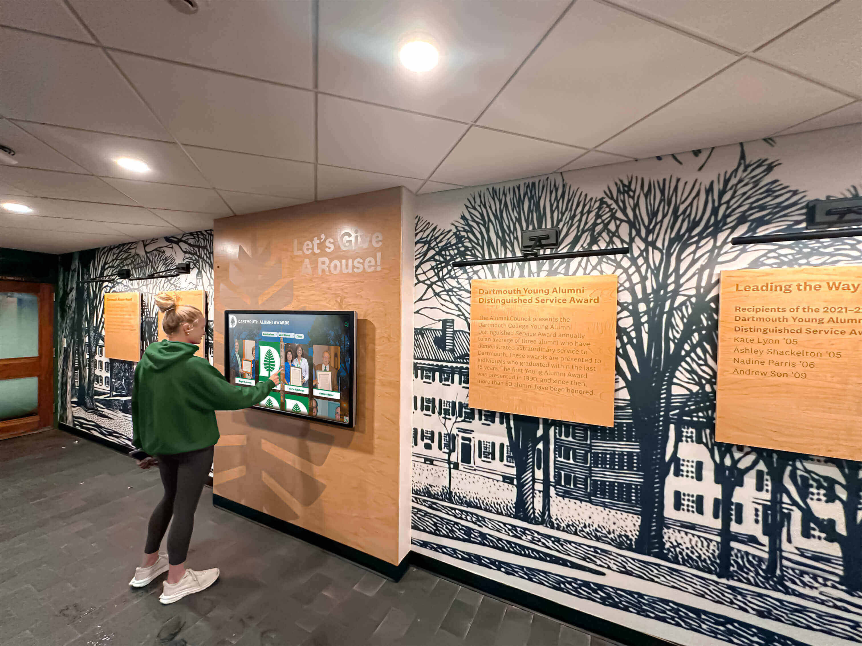
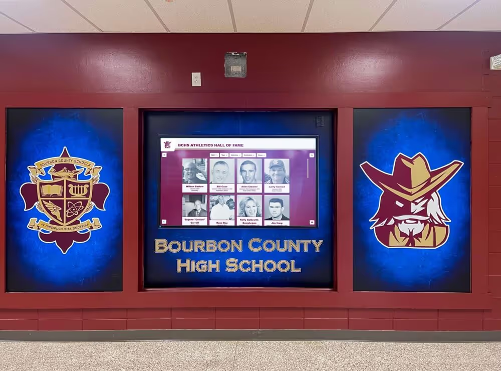
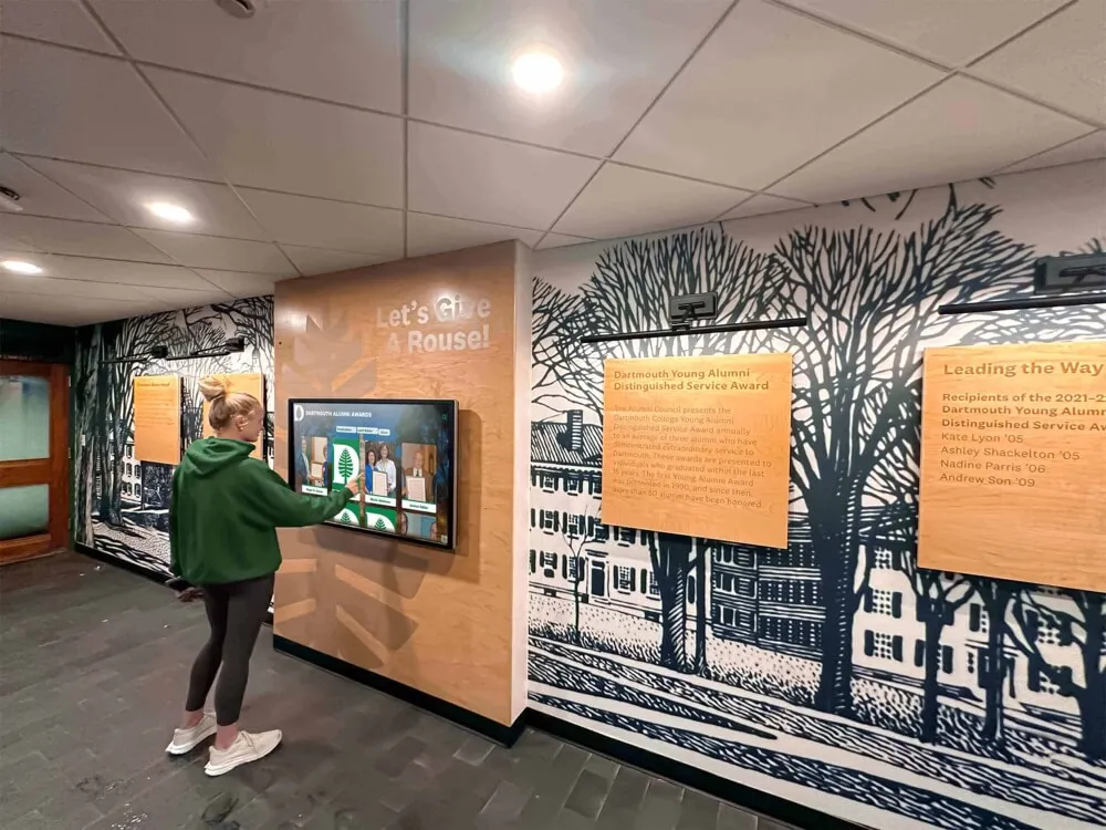
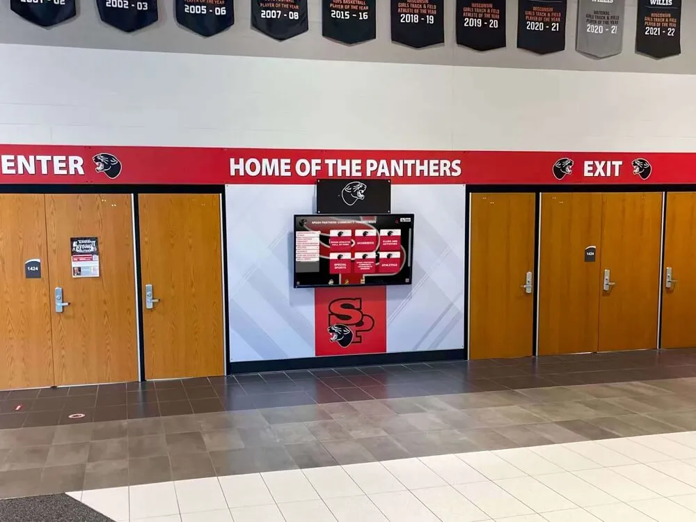
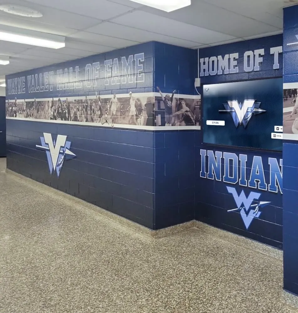
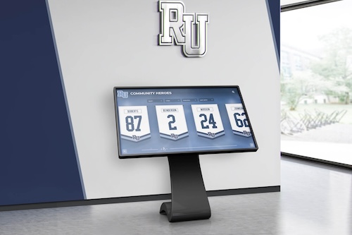
Students and visitors rely on recognition displays being operational throughout the events where achievement is celebrated—RSTP convergence testing is the network-layer verification that confirms the switching infrastructure recovers fast enough to keep that experience uninterrupted
A school recognition display RSTP convergence test is a one-to-two-hour investment that documents exactly how quickly the display’s network recovers from a link failure, confirms the spanning tree configuration is correct across every switch in the path, and establishes the convergence baseline against which future tests can compare. Building this test into the pre-event IT checklist adds the spanning tree layer to the network verification practice, alongside DHCP reservation confirmation, VLAN isolation checks, and content platform connectivity testing—completing the infrastructure verification that recognition programs depend on to run without interruption.
See a School Recognition Display in Action
If your school is evaluating or deploying a touchscreen recognition display and wants to understand the full network integration—RSTP configuration, VLAN design, PoE switch requirements, and cloud platform connectivity—a live demonstration gives your IT team and athletic director those answers before installation. Rocket Alumni Solutions builds recognition display platforms designed for school network environments, with documented infrastructure requirements and technical teams who can walk through spanning tree and network integration questions alongside your IT coordinator.