

A recognition display RS-232 control test is the structured process of sending serial commands to a school recognition display, confirming that each command produces the correct response, and verifying that the display recovers predictably when communication fails or commands are malformed. RS-232 serial control is the most widely supported method for remotely managing commercial displays—powering them on and off on a schedule, switching inputs between recognition content and live announcements, adjusting brightness for morning versus afternoon lobby conditions, and confirming operational status without physically touching the screen. For AV integrators, facilities teams, and IT staff commissioning a school hall of fame installation or athletic recognition display, completing a documented RS-232 control test before turnover is what distinguishes a system that will run reliably for years from one that surfaces mysterious failures six months after the installer has left the building.
This guide walks through every stage of a complete recognition display RS-232 control test: physical connection verification, terminal software configuration, the sequence of commands to test at commissioning, how to read and document the display’s feedback responses, and a structured recovery protocol for the most common RS-232 failure modes encountered on school recognition displays.
RS-232 has been a standard for serial communication since the 1960s, and it remains the dominant out-of-band control channel for commercial-grade flat-panel displays precisely because it does not depend on the network, does not require the display’s operating system to be running, and works when the display is in a powered-off standby state. A school recognition display installed in a lobby hallway may lose its network connection, have its CMS app restart, or be switched to a different content source—but RS-232 remains functional through all of it, which is why commissioning a thorough RS-232 control test matters even when most day-to-day management will happen through software.

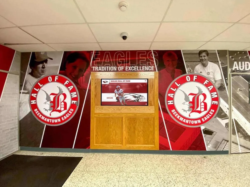
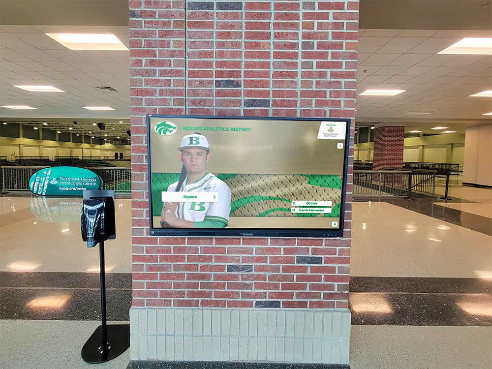
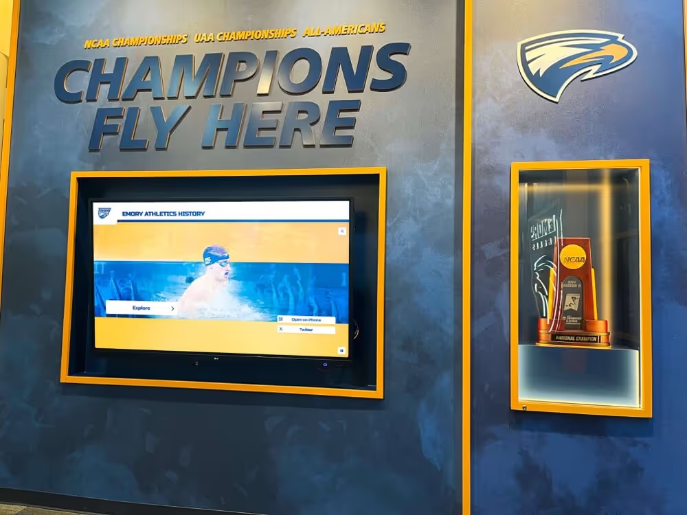
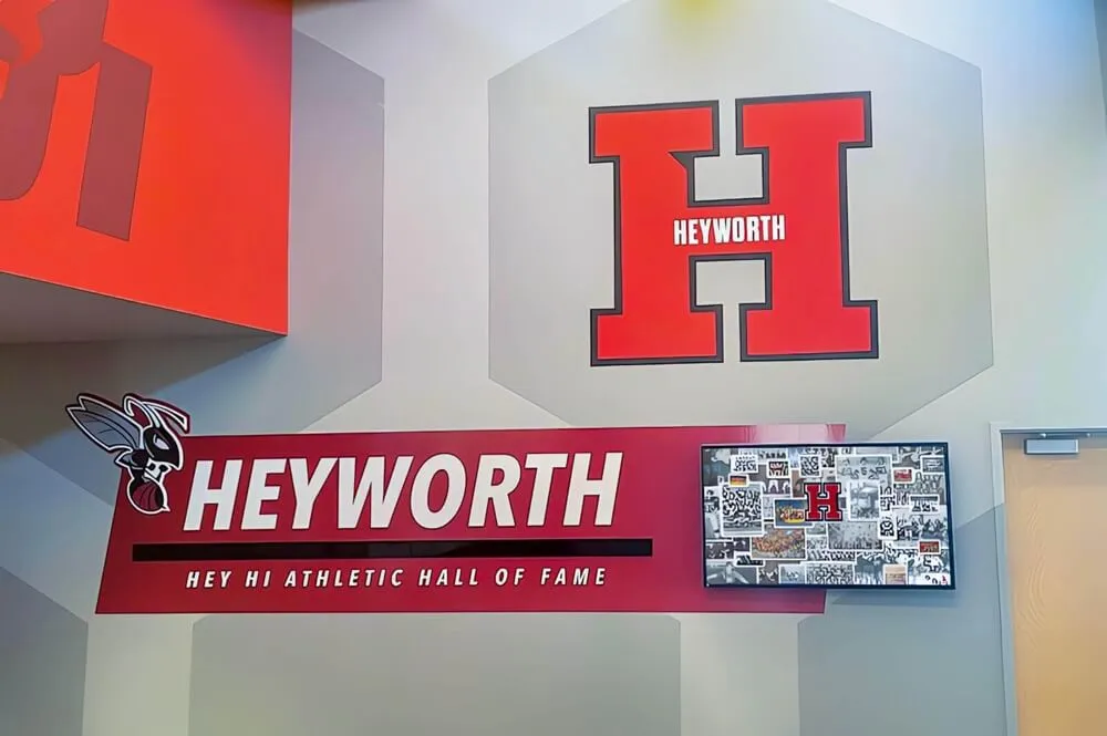
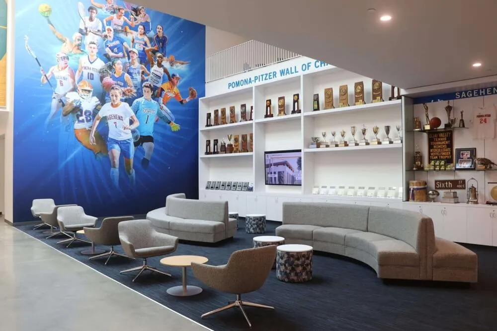
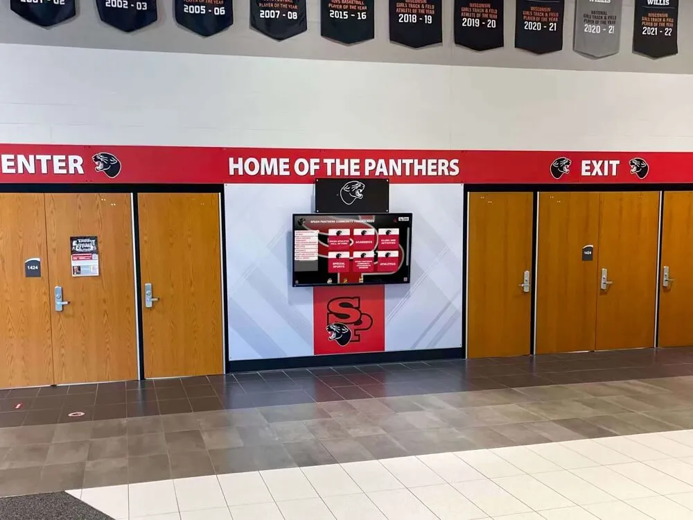
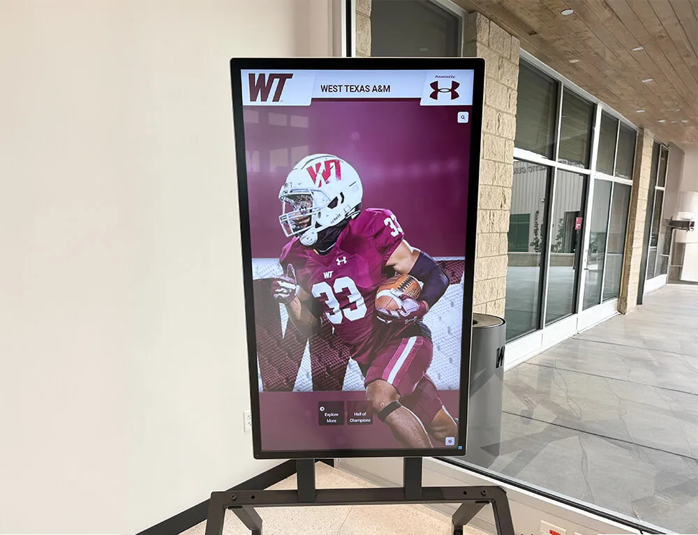
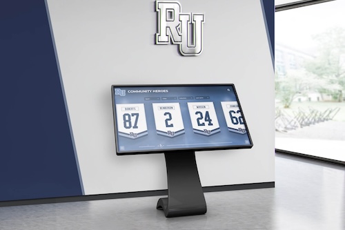
Athletic recognition kiosks like this one require reliable remote control for scheduled power cycling and input switching—RS-232 provides that control independently of the network and operating system
What RS-232 Serial Control Does for a Recognition Display
Commercial recognition displays in school athletic programs are not consumer televisions. They are commercial-grade panels designed for continuous operation in high-traffic lobbies, gymnasium hallways, and main entrance corridors, and they include a serial control port specifically to allow a building management system, a scheduling controller, or a technician’s laptop to issue commands that the remote control or touchscreen cannot easily provide on a schedule.
RS-232 serial control allows a facilities team or AV system to:
- Power the display on and off on a daily schedule without depending on a network connection or a software automation platform that can fail
- Switch inputs between the recognition content source and a live video feed for game nights or assemblies
- Query operational status—current power state, selected input, current volume level—from a central monitoring point without sending someone to physically check the display
- Adjust brightness automatically based on time of day, reducing backlight intensity during evening hours to extend panel life and reduce energy consumption
- Mute or unmute audio on a lobby display that plays athletic highlight audio during arrival periods but should be silent during scheduled quiet times
- Trigger a factory input reset if the display locks on a non-recognition source and the on-site contact cannot locate the remote control
For schools that have built out comprehensive recognition programs—with athlete profiles, championship records, and athletic archive materials organized by sport and season—the content system only delivers its value when the display is reliably powered, correctly sourced, and at the right brightness for the time of day. RS-232 control is the mechanism that makes that reliability automatic.
Physical Connection: Verifying the Cable and Port
RS-232 on most commercial display panels uses either a DE-9 connector (the 9-pin connector commonly called DB-9) or a 2.5 mm or 3.5 mm stereo audio jack wired to carry RS-232 signals. Confirm which connector your display uses before ordering cable. Wiring a standard audio plug to carry RS-232 requires a cable specifically made for that display model—a standard audio cable will not work and can damage the control port.
Cable type: null modem vs. straight-through
This is the single most common physical wiring mistake in display RS-232 commissioning. When connecting a laptop’s RS-232 port (or a USB-to-RS-232 adapter) directly to a display’s RS-232 input:
- Use a null modem cable if the display manufacturer’s documentation specifies it. A null modem cable crosses the transmit (TX) and receive (RX) lines so that each device’s transmit pin connects to the other’s receive pin.
- Use a straight-through cable (also called a direct cable) if the manufacturer specifies it or if the display’s RS-232 port is wired as DCE (Data Communications Equipment) rather than DTE (Data Terminal Equipment).
The display’s installation manual will specify which type to use. If the documentation is unavailable, try a null modem cable first—it is correct for the majority of commercial display RS-232 ports.
Connection checklist before sending any command:
- Confirm that the RS-232 port on the display panel is labeled—some displays include both an RS-232 IN and an RS-232 OUT port for daisy-chaining; connect to RS-232 IN
- Verify that the USB-to-RS-232 adapter, if used, is recognized by the operating system and assigned a COM port (Windows Device Manager → Ports)
- Confirm the cable type matches the manufacturer’s specification
- Confirm the display is plugged in and in standby (not hard-powered off at the surge protector)—most commercial displays respond to RS-232 power-on commands only when in standby, not when fully de-energized
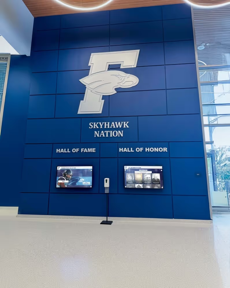
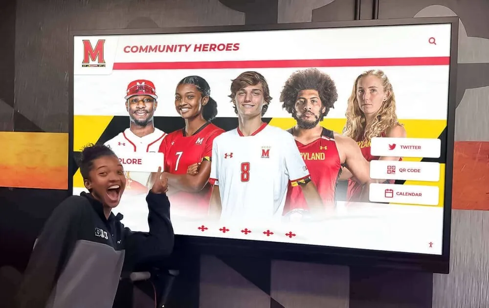
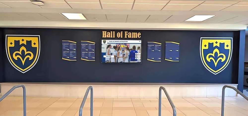
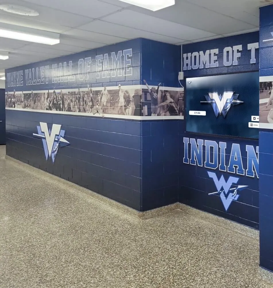
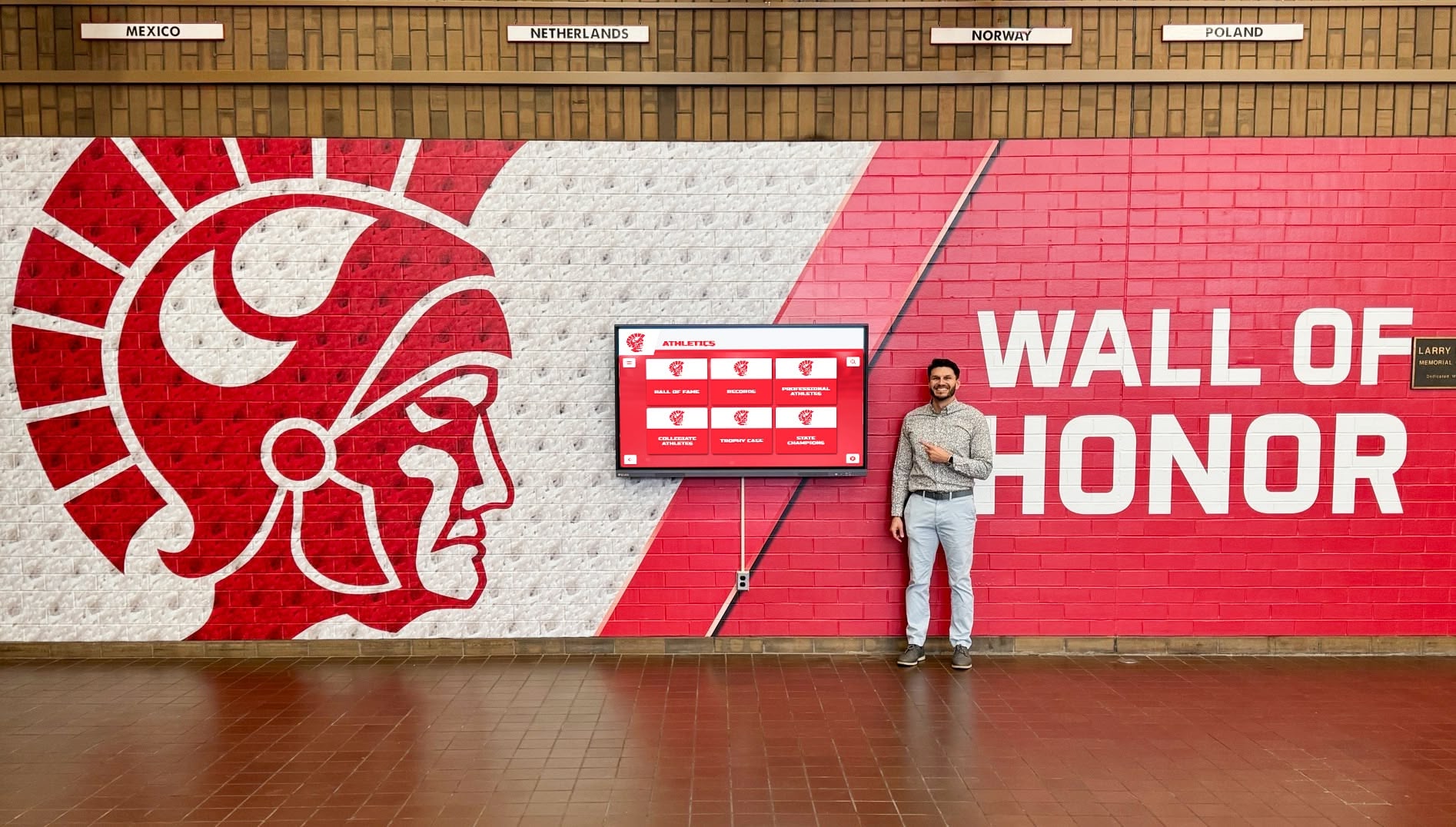
Commercial recognition displays include RS-232 ports specifically for remote management—verifying physical connection is the first step in any commissioning test sequence
Terminal Software Configuration
For a recognition display RS-232 control test, any terminal emulator that allows manual hex or ASCII command entry will work. Common free options include PuTTY (Windows), CoolTerm (Windows/Mac), and Tera Term (Windows). Serial terminal apps are also available for macOS and Linux.
Serial port settings to configure:
| Parameter | Typical Setting | Notes |
|---|---|---|
| Baud rate | 9600 | Most common; some displays use 19200, 38400, or 115200—check the manual |
| Data bits | 8 | Standard for nearly all commercial displays |
| Parity | None | Rarely used on commercial display RS-232 |
| Stop bits | 1 | Standard; occasionally 2 on older models |
| Flow control | None | Hardware flow control (RTS/CTS) is a common misconfiguration source |
8N1 (8 data bits, no parity, 1 stop bit) at 9600 baud is the correct starting point for the majority of commercial recognition displays. If commands are sent but no response is received, the first thing to change is the baud rate—try 19200, then 38400, then 115200 before concluding that the physical connection is wrong.
Flow control is the most common software configuration mistake. Commercial display RS-232 ports typically do not implement RTS/CTS hardware flow control. If the terminal software is configured to use hardware flow control and the display does not drive RTS/CTS, the software will wait indefinitely for a flow control signal that never arrives, and no commands will be sent. Set flow control to None.
Local echo: Many terminal applications can display the characters you type as you type them (local echo). This is useful for verifying that keystrokes are being captured, but it means that what you see in the terminal window includes your command followed by the display’s response. Turn local echo off if the display echoes commands back itself—you will otherwise see doubled output that is difficult to read.
The Command Sequence to Test at Commissioning
Not all RS-232 display commands are structured the same way. Some manufacturers use ASCII text strings; others use hexadecimal byte sequences. The display’s RS-232 command set documentation will specify both the command format and how to interpret the response. If that documentation is not available, the manufacturer’s technical support team can usually provide it—most commercial display brands publish command sets for their current and recent product lines.
A complete commissioning test should verify these functions in the following order:
Test 1: Power Status Query
Before sending any control command, query the display’s current power state. This confirms that the serial connection is working before you attempt to change anything.
Most commercial displays respond to a status query with a response that indicates the current power state (on, standby, or warming up). Verify that the response matches the known state of the display before proceeding.
- Send the power status query command
- Confirm that a response is received within 2 seconds
- Confirm that the response matches the display’s observed state (standby light is visible → response should indicate standby)
- Document the raw response string for the commissioning log
Test 2: Power On Command
With the display in standby, send the power-on command and time how long the display takes to reach full operation.
- Send the power-on command
- Start a timer at the moment the command is sent
- Confirm that the display begins the warm-up sequence within 3 seconds of the command
- Confirm that the display reaches full operation within the manufacturer’s specified warm-up time (typically 10–45 seconds for commercial panels)
- After the display is fully on, query power status again and confirm the response now indicates the powered-on state
- Document the warm-up time in the commissioning log
Test 3: Input Selection
Recognition displays typically connect to a media player or dedicated recognition content source on a specific HDMI input, with additional inputs available for auxiliary sources (a camera feed, a laptop for presentations, or a live game broadcast). Verify that RS-232 input switching works for all inputs the facility intends to use.
- Confirm the current active input by observation or by sending an input status query
- Send the command to switch to the recognition content input (e.g., HDMI 1)
- Confirm visually that the input changes within 3 seconds
- Send the command to switch to each additional input the facility uses and confirm each switch
- Return to the recognition content input and confirm
- Document all tested inputs and their RS-232 command codes
Test 4: Volume Control
If the recognition display plays audio—highlight reels, ceremony recordings, or ambient music during arrival periods—volume control through RS-232 enables scheduled quiet hours and event-mode adjustments without requiring on-site staff.
- Send a volume-down command and confirm the display’s on-screen volume indicator decreases
- Send multiple volume-down commands and confirm each step responds correctly
- Send a volume-up command and confirm the indicator increases
- Send the mute command and confirm audio is silenced
- Send the unmute command and confirm audio is restored
- Document the command codes and confirm they match the manufacturer’s documentation
Test 5: Brightness and Backlight Control
Lobby recognition displays in school hallways face significant ambient light variation between morning, midday, and evening. RS-232 brightness control enables a building automation system or simple scheduling controller to reduce backlight during evenings, extending panel life and reducing energy consumption.
For programs that have integrated their alumni recognition archives into a lobby display, consistent panel brightness also affects the visual quality of historical photos and athlete profile images—particularly older images that may not have been captured at high resolution.
- Send a brightness-down command and confirm the display’s backlight visibly decreases
- Send a brightness-up command and confirm the display responds
- Query the current brightness level if the display supports brightness status queries
- Document the minimum and maximum brightness command codes and their observed effects
Test 6: Power Off Command
- Send the power-off command
- Confirm the display enters standby within 5 seconds
- Query power status and confirm the response indicates standby
- Wait 30 seconds, then send the power-on command and confirm the display powers back on
- Document the power-off response and standby confirmation behavior
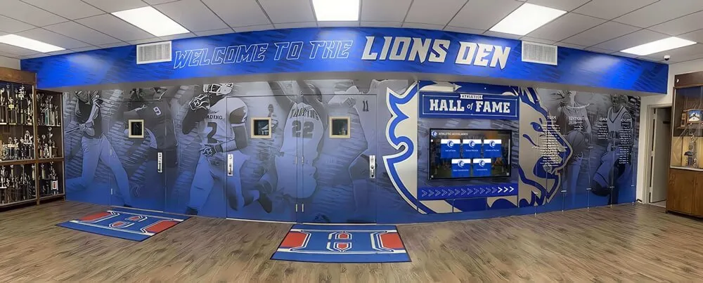
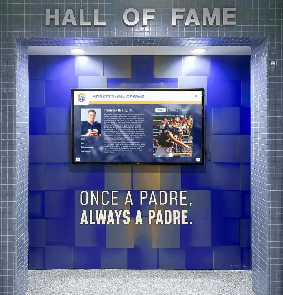
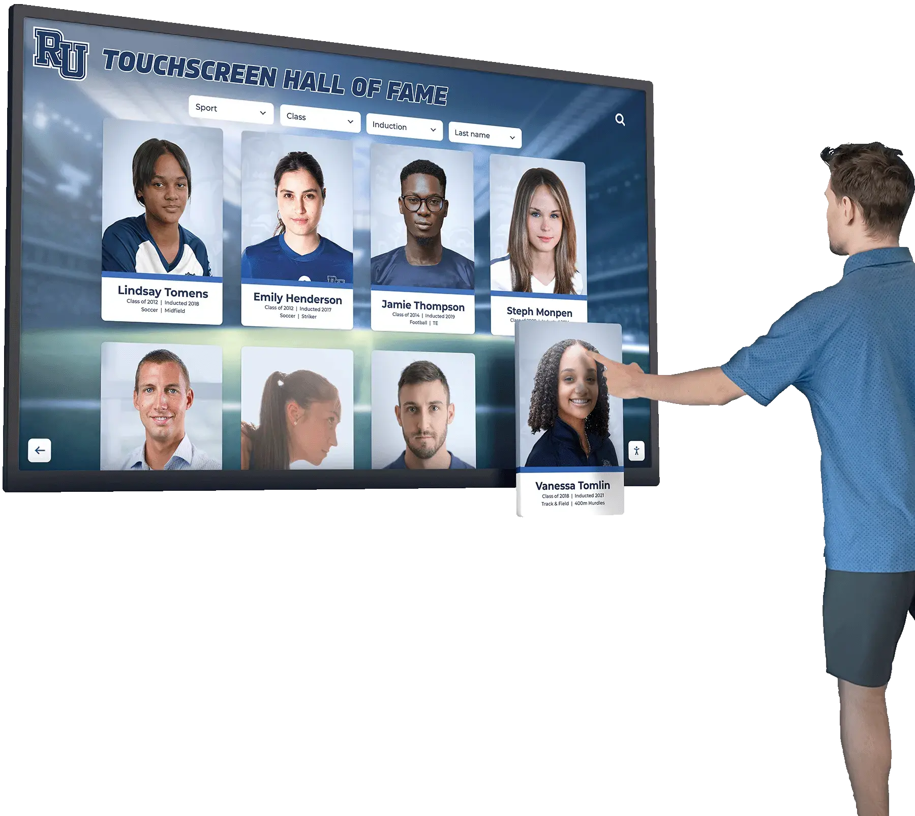
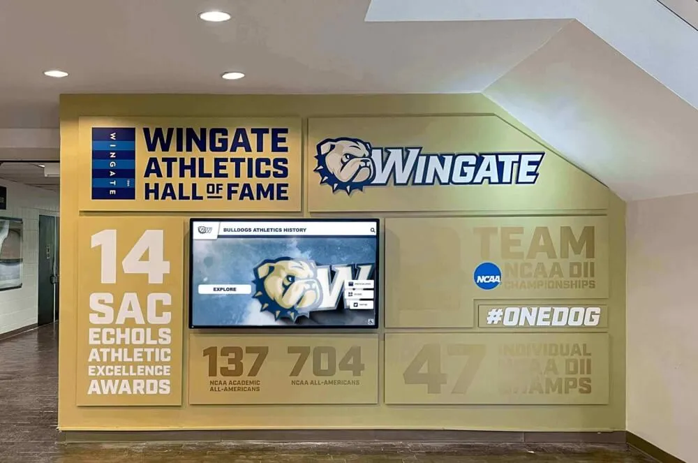
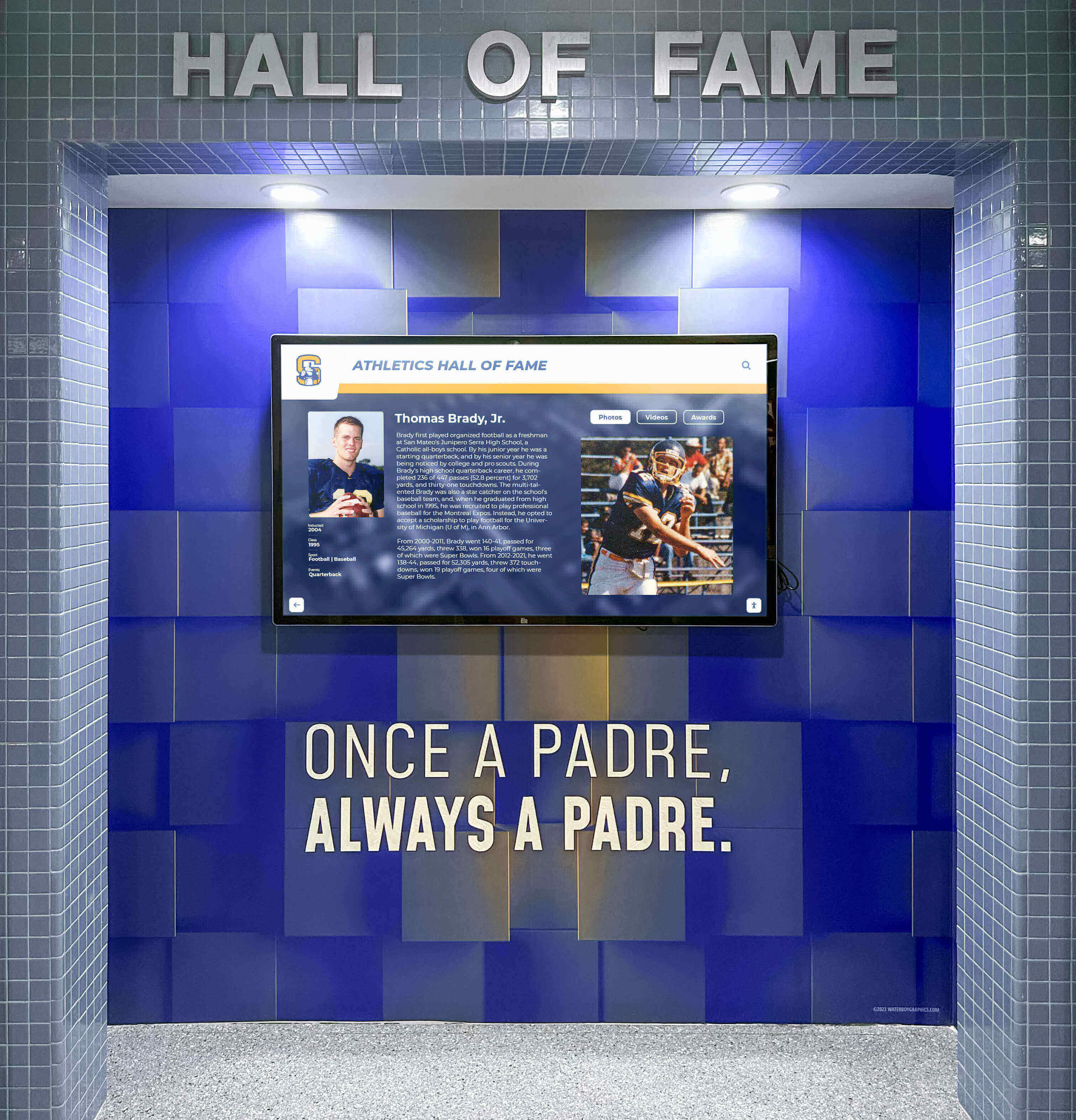
School recognition programs invest significant effort in designing and installing athletic hall of fame displays—commissioning a complete RS-232 control test protects that investment by verifying remote management before the installer leaves the building
Reading and Documenting Feedback Responses
A display that accepts commands without responding is harder to troubleshoot than one with clear feedback. Commercial displays use several response patterns; knowing which one your display uses is essential before the commissioning test.
ACK/NAK responses: Some displays respond to every command with an acknowledgment byte (ACK, typically 0x06) on success or a negative acknowledgment byte (NAK, typically 0x15) on failure. If your display uses ACK/NAK, every command in the test sequence should produce an ACK. A NAK indicates the command was received but rejected—typically because the command code is wrong, the display is in a state where the command cannot be applied (for example, sending a volume command when the display is in standby), or the command was malformed.
Echo responses: Many displays echo the received command back to the sender followed by a status byte or status string. Confirm that the echoed command matches what was sent—a mismatch indicates that the display received a garbled version of the command, usually caused by a baud rate mismatch or cable issue.
Status string responses: Some displays return a human-readable or structured status string after specific query commands. Document the exact response string for each query in the commissioning log.
No response: If a command produces no response at all, the physical connection, baud rate, or cable type is likely wrong. Work through the physical connection checklist before changing command codes.
Commissioning log format for RS-232 test results:
| Command Tested | Command Sent (hex or ASCII) | Expected Response | Received Response | Pass/Fail | Notes |
|---|---|---|---|---|---|
| Power Status Query | (command code) | (expected) | (actual) | ||
| Power On | (command code) | (expected) | (actual) | ||
| HDMI 1 Select | (command code) | (expected) | (actual) | ||
| HDMI 2 Select | (command code) | (expected) | (actual) | ||
| Volume Down | (command code) | (expected) | (actual) | ||
| Mute | (command code) | (expected) | (actual) | ||
| Brightness Down | (command code) | (expected) | (actual) | ||
| Power Off | (command code) | (expected) | (actual) | ||
| Power On (recovery) | (command code) | (expected) | (actual) |
Keep the commissioning log with the display’s other installation documentation—cable diagrams, mount hardware specifications, and content system login credentials. Facilities teams responding to a display failure months later will need the documented command codes and the confirmed baud rate to reconnect and diagnose without calling the integrator.
Schools that manage multiple recognition displays across a campus—from a main lobby athletic hall of fame to academic honors displays along classroom corridors—benefit from a standardized commissioning log template applied consistently to every display so that any staff member can service any display from the same reference document.
Rocket Alumni Solutions builds touchscreen halls of fame and digital recognition displays designed for school athletic programs and recognition committees. If you are commissioning a recognition display and want to see how the platform’s content system works alongside your building’s AV control infrastructure, request a live demo to see the display management workflow in action.
Common RS-232 Failure Modes and Recovery Procedures
A well-documented commissioning test reveals failure modes early, when they are straightforward to correct. The following recovery procedures address the most common RS-232 failures encountered on school recognition displays.
Failure: No Response to Any Command
Likely causes: Wrong baud rate, wrong cable type (null modem vs. straight-through), COM port not recognized by the operating system, USB-to-RS-232 adapter driver not installed, flow control mismatch.
Recovery procedure:
- Verify the USB-to-RS-232 adapter appears in Device Manager under Ports with a COM port number
- Confirm the terminal software is connected to that specific COM port number, not to a different COM port
- Change the baud rate in the terminal software to 19200; send the power status query again
- If still no response, change to 38400, then 115200
- If no baud rate produces a response, disconnect and reconnect the cable; swap for a null modem cable if a straight-through was in use (or vice versa)
- Confirm the display is in standby (not hard-powered off at the surge protector)—a display that is fully de-energized will not respond to RS-232 commands
Failure: Commands Received but Responses Are Garbled
Likely causes: Baud rate mismatch between the display and the terminal software. If the configured baud rate is close but not exactly correct, the display and the terminal may synchronize on some bytes and lose synchronization on others, producing responses with correct structure but wrong characters.
Recovery procedure:
- Try baud rates both above and below the current setting—9600, 19200, 38400
- Confirm that data bits, parity, and stop bits are set to 8N1—a mismatch in any of these parameters produces garbled output
- Turn local echo off in the terminal software if it is on, to ensure that what appears in the terminal window is the display’s response rather than a mix of your command and the response
Failure: Power-On Command Accepted but Display Does Not Turn On
Likely causes: The display requires a specific warm-up delay before accepting a second power-on command after a previous power-off. Some commercial panels enter a protection mode if power-on commands are sent too rapidly after power-off and require a 30-to-60-second delay.
Recovery procedure:
- Wait 60 seconds after the most recent power-off or power-on command before retrying
- Query power status before sending the power-on command to confirm the display is in standby and not in a thermal or protection hold state
- Confirm that the display is in AC standby (standby LED lit) rather than fully de-energized—power-on RS-232 commands require standby mode
Failure: Input-Select Command Accepted but Display Does Not Switch
Likely causes: The display may not accept input-select commands while a signal is not present on the target input. Some commercial panels only switch to an input if a live signal is detected on that input, ignoring RS-232 input commands when the target input has no connected source.
Recovery procedure:
- Confirm that the content source on the target input is powered on and actively outputting a signal
- Check whether the display has an “Auto Input Search” or “Input Signal+” setting that may be overriding the RS-232 input command—disable it during the commissioning test
- Try the input command again with a confirmed active source on the target input
- Document whether the display requires an active signal to execute RS-232 input-select commands—this is a behavior the scheduling controller needs to account for in automated programming
Failure: RS-232 Communication Works Initially but Fails After Network or CMS Changes
Likely causes: On some commercial display models, certain software updates or CMS configurations reset the RS-232 baud rate to a default value that differs from the value at commissioning. A CMS-pushed firmware update is the most common trigger for this.
Recovery procedure:
- Confirm the current RS-232 baud rate setting in the display’s on-screen menu (usually under System → Serial Control or Connections → RS-232)
- Update the terminal software and the scheduling controller’s configuration to match the current baud rate
- Re-run the full commissioning command test sequence to confirm all functions are operational at the new baud rate
- Document the firmware version at which the baud rate changed so that future firmware updates can be evaluated for the same behavior
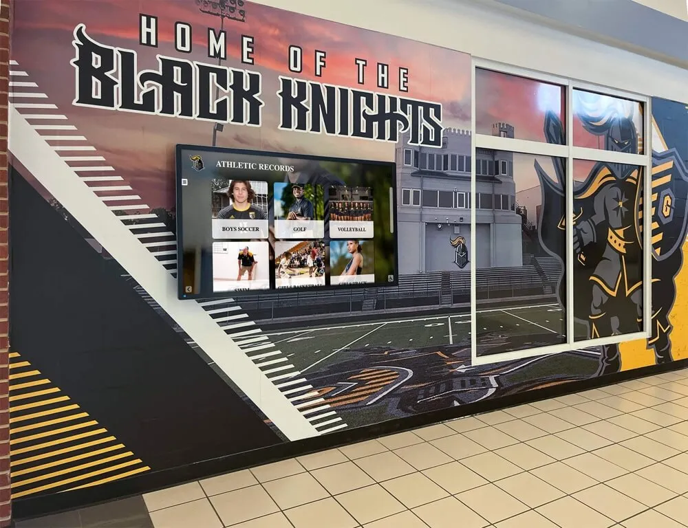
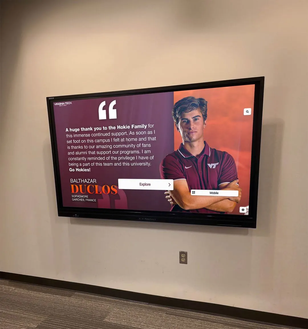
Facilities teams managing school athletic recognition displays need a documented RS-232 command set to handle power, input, and brightness failures without calling in the AV integrator for every issue
Daisy-Chaining Multiple Recognition Displays
Many school athletic facilities install multiple recognition displays along a corridor, in a gymnasium lobby, or across multiple trophy and awards areas. Commercial displays that support RS-232 daisy-chaining allow a single RS-232 source—a laptop, a building automation controller, or a scheduling device—to address multiple displays through a single serial connection.
How daisy-chaining works:
The RS-232 OUT port on the first display connects to the RS-232 IN port on the second display, which connects to the RS-232 IN port on the third, and so on. Each display in the chain is assigned a unique display ID, and commands include the target display ID so that each display responds to commands addressed to it and passes through commands addressed to other displays in the chain.
Commissioning a daisy-chained installation requires:
- Confirming that each display in the chain has a unique display ID set in its on-screen menu (typically under System → Display ID or Serial Control → ID)
- Confirming that each display in the chain is set to the same baud rate and serial parameters
- Testing a command addressed to display ID 1 and confirming only display 1 responds
- Testing a command addressed to display ID 2 and confirming only display 2 responds
- Testing a broadcast command (if the manufacturer supports a broadcast address) and confirming all displays respond simultaneously
- Documenting which physical display location corresponds to which display ID in the commissioning log
For schools whose alumni recognition programs span multiple zones—alumni engagement programs that extend beyond a single lobby display to cover an entire athletic corridor or multi-floor building—daisy-chain RS-232 control simplifies daily operations significantly, allowing a single scheduled power-on command to bring up all displays in sequence at the same time each morning.
Integrating RS-232 Control with a Scheduling System
The full operational value of RS-232 control is realized when power-on and power-off commands are automated through a scheduling system rather than issued manually. For most school recognition display installations, this means one of three approaches:
Approach 1: Building Automation System (BAS) integration. Many school buildings operate a BAS that controls lighting, HVAC, and access systems on a time-based schedule. Some BAS platforms support RS-232 output directly, allowing recognition displays to be scheduled alongside lighting zones in the same interface the facilities team already manages.
Approach 2: Dedicated AV control system. AV controllers from manufacturers such as Crestron, Extron, and AMX support RS-232 output and can be programmed to schedule display power commands with precise timing. These controllers can also respond to event triggers—a game-day contact closure, a motion sensor at the lobby entrance, or a calendar event from the school’s scheduling software.
Approach 3: Simple serial scheduling devices. For installations where a full AV control system is not in the budget, dedicated RS-232 scheduling controllers are available at lower cost. These devices connect to the display’s RS-232 port, store a library of commands, and execute them on a weekly schedule. They are sufficient for simple power-on/power-off automation when more sophisticated event-based control is not required.
Whichever approach the installation uses, the commissioning RS-232 test sequence should be run again from the scheduling system after integration—not just from a laptop terminal. Commands that work correctly from a terminal emulator can fail from a scheduling controller if the controller’s output buffer size, line-ending format, or inter-command delay differs from what the display expects. The test from the terminal verifies the display; the test from the scheduling system verifies the complete operational workflow.
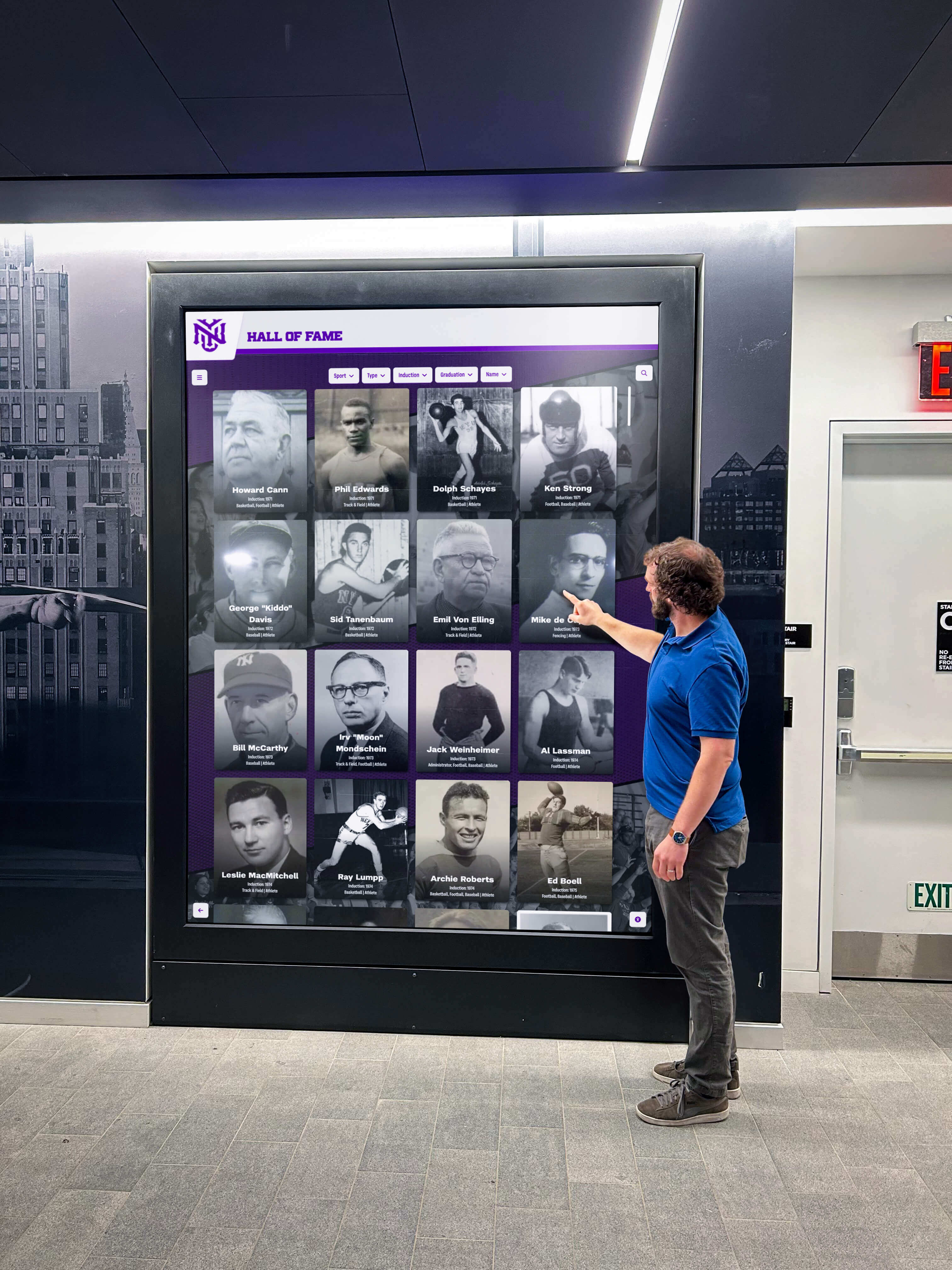
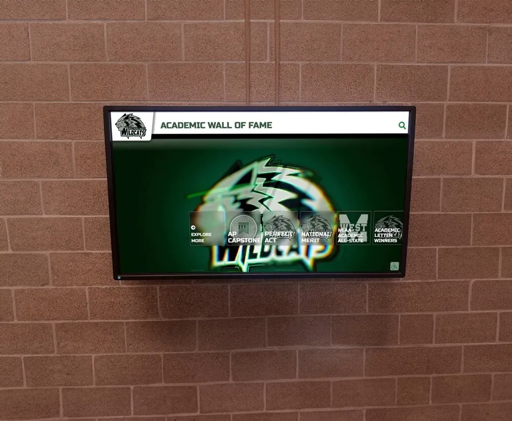
Automated RS-232 scheduling ensures that recognition displays are powered on and showing content during all operating hours without requiring staff to manually manage the display each morning
Pre-Turnover Documentation Package
Before an integrator turns a recognition display installation over to facilities staff, the RS-232 commissioning documentation package should include:
Required documents:
- Display manufacturer, model number, and firmware version at commissioning
- RS-232 connection type (null modem or straight-through), connector type (DE-9, 2.5 mm, or 3.5 mm), and cable length
- Confirmed serial parameters: baud rate, data bits, parity, stop bits, flow control
- Complete commissioning command log with all tested commands, their hex or ASCII codes, expected responses, and actual responses
- Display ID assignments for any daisy-chained installation
- Recovery procedures for each documented failure mode
- Scheduling controller make, model, and the current programmed schedule
- Contact information for the display manufacturer’s technical support line and the integrator’s support contact
Recommended additions:
- A one-page quick-reference card covering power-on, power-off, input select, and volume commands in plain language for facilities staff who are not AV technicians
- Screenshots of the terminal software configuration for the confirmed settings, so a new staff member can reconfigure a replacement laptop without guessing
- A copy of the display’s RS-232 command reference document, even if it is also available online—manufacturer websites reorganize periodically and a locally saved copy remains accessible when the online version is not
Recognition programs that invest in thorough commissioning documentation—alongside the alumni history and sports memorabilia that anchor the display’s content—protect the long-term operational reliability of the installation. The content is only as accessible as the display’s ability to be powered on and showing the right source when students, alumni, and visitors arrive.
Frequently Asked Questions
Does a recognition display need to be on for RS-232 commands to reach it?
No—this is one of RS-232’s key advantages. Commercial displays in standby mode continue to monitor the RS-232 port and respond to power-on commands. The display must be connected to AC power and in standby (not hard-powered off at the surge protector or wall outlet), but it does not need to be showing an image for RS-232 commands to be processed.
What is the difference between RS-232 and RS-485 for display control?
RS-232 is a point-to-point protocol—one device connects to one display. RS-485 is a differential, multi-drop protocol that can connect a single controller to many devices on one cable run at longer distances. Some commercial display installations in large school facilities use RS-485 for long cable runs and multi-display control. The commissioning test process is similar, but RS-485 requires matching the termination resistance and addressing scheme for each display in the chain. Confirm which protocol your display’s control port uses before purchasing cable.
Our display accepts power commands but does not respond to input-select commands. Why?
Input-select commands on many commercial displays require an active signal on the target input before the switch will execute. Confirm that the content source on the target input is powered on and outputting a signal. Also check whether the display’s “Auto Search” or “Auto Input” setting is enabled—this setting causes some displays to ignore RS-232 input commands in favor of their own signal-detection logic.
Can we use the same RS-232 commands in our building automation system that worked in the terminal emulator?
The commands will be the same, but verify that the building automation system sends them with the same line endings, inter-byte timing, and inter-command delay. Some displays require a carriage return (CR), a carriage return plus line feed (CRLF), or a specific termination byte after each command. If commands worked in the terminal emulator but fail from the BAS, the most likely cause is a difference in line-ending format or command pacing.
How often should we re-run the RS-232 commissioning test after initial turnover?
Run the full test sequence after any firmware update to the display, after any change to the scheduling controller’s programming, and after any service event that involved the display’s RS-232 port or the cable connecting it. An annual check as part of the facility’s summer-break AV maintenance schedule is also a good practice for identifying baud rate resets or cable degradation before they cause a visible failure during the school year.
The display’s command documentation lists different commands for different firmware versions. How do we know which version applies?
Check the display’s firmware version in the on-screen menu under System → About or Information → Software Version. Cross-reference that version number against the command documentation to confirm which command table applies. Record the firmware version in the commissioning log so that future staff can identify the correct command table without needing to navigate the menu.
For school programs that maintain detailed digital records of athletic history and recognition archives, the same documentation discipline that applies to athlete profiles and championship records applies to the AV systems that display them—a reference document that exists is far more valuable than one that was meant to be created later.
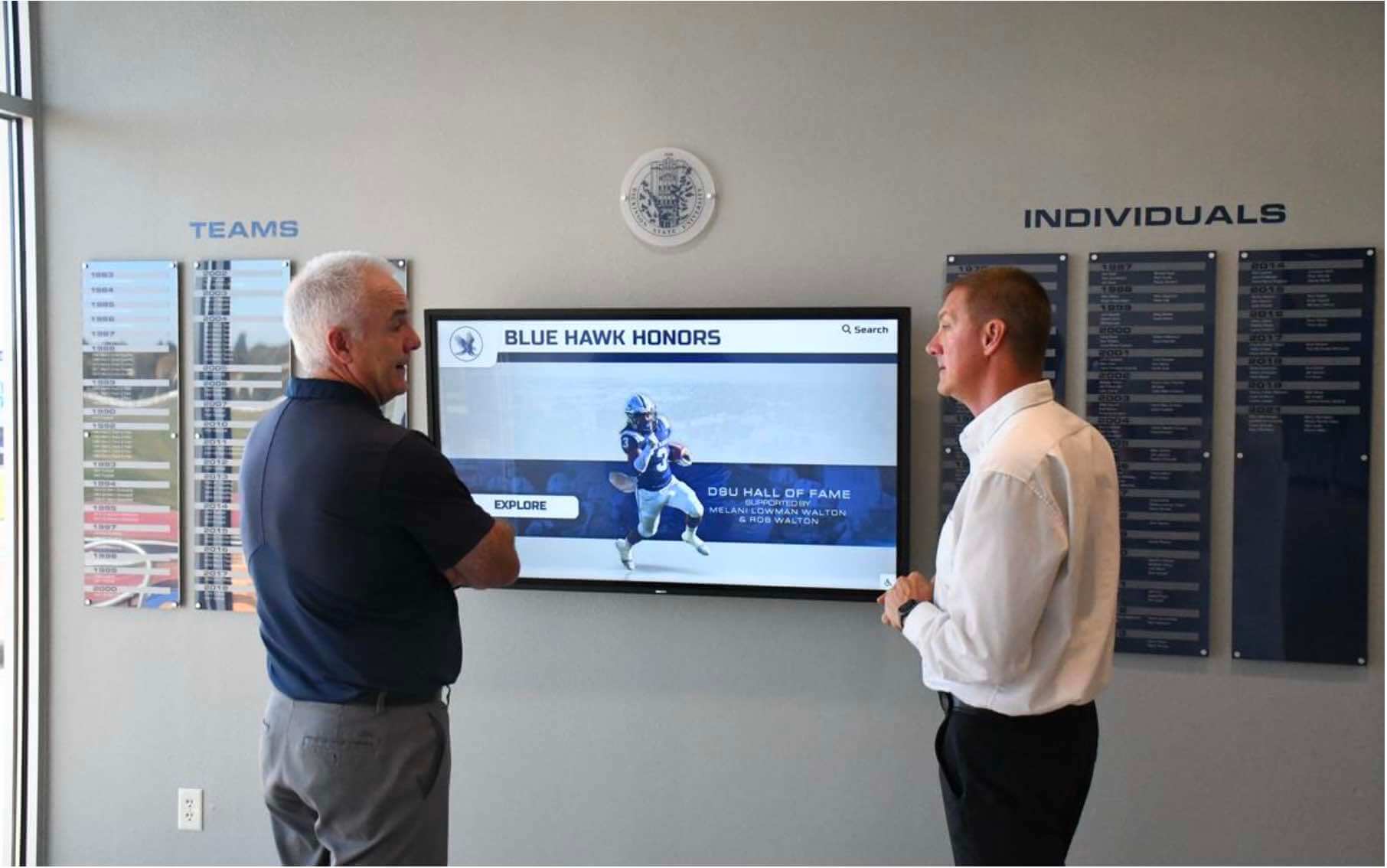
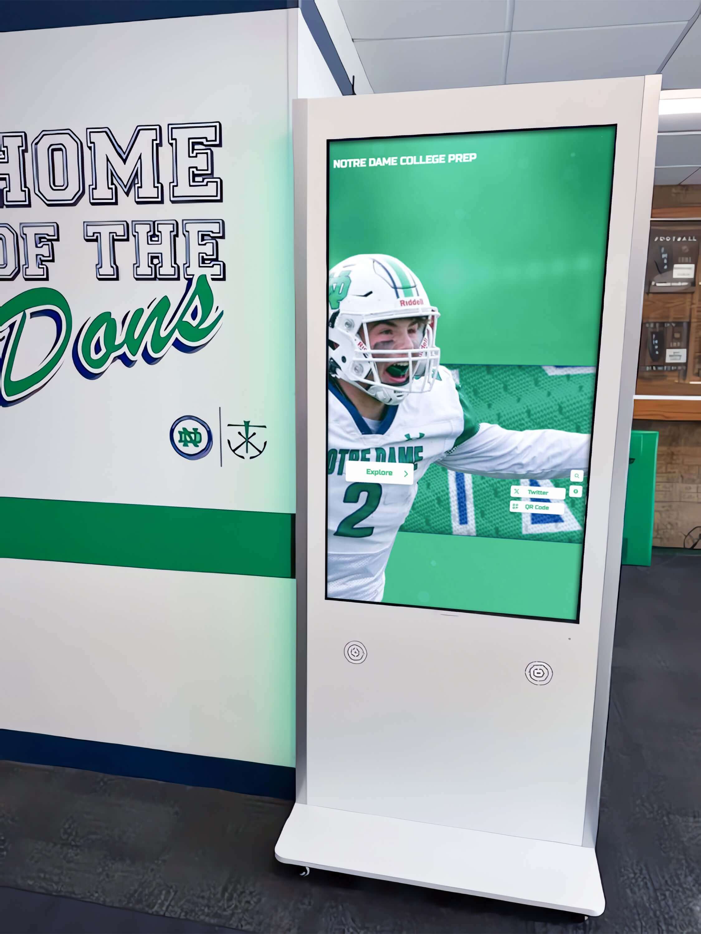
A well-commissioned and documented RS-232 control system ensures that school recognition displays remain powered on, correctly sourced, and displaying athletic history for every visitor—without depending on manual intervention each day
Connecting RS-232 Testing to the Broader Recognition Display Commissioning Checklist
RS-232 control testing is one component of a complete recognition display commissioning process. It belongs alongside network configuration and CMS setup, content system login verification, speaker and audio level testing, ambient light sensor calibration, and emergency contact documentation.
Schools that approach their recognition display installations as complete systems—not just hardware installations—treat each commissioning step as a requirement rather than a recommendation. For athletic directors and facilities coordinators managing displays that will showcase decades of school athletic achievement, championship records, and student recognition, the content on the display represents irreplaceable institutional history. The control system that keeps it running reliably is what ensures that history remains visible.
A recognition display that powers on automatically each morning, switches to the correct source, adjusts brightness to the current ambient light level, and powers down in the evening without any staff involvement is a display that does its recognition work continuously—for athletes, coaches, administrators, and visitors alike—without the gaps that manual management always creates.
Rocket Alumni Solutions designs and deploys touchscreen halls of fame and digital recognition displays built for school athletic programs, recognition committees, and alumni offices. If your school is planning or commissioning a recognition display installation and wants to see how the content management system, display hardware, and remote control capabilities work together, request a live demo and see the complete system in action with your school’s content.